Waveshare RP2350-LCD-1.28
Overview
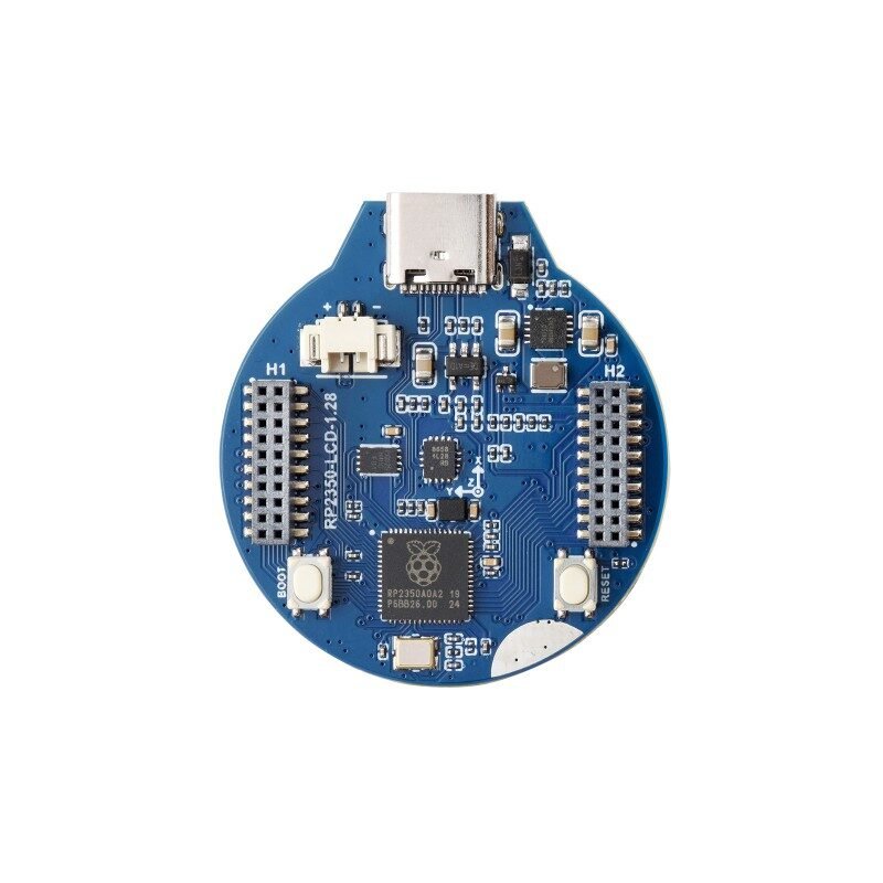
A round MCU board built around the Raspberry Pi RP2350 chip with a 1.28“ round IPS LCD, a 6-axis IMU, and Li-ion battery charge management all integrated on one small (Φ~32.4mm active display) circular PCB. Same display driver chip (GC9A01A) as the GC9A01 1.28“ round LCD already in this library, but here it’s soldered directly to the MCU board rather than a separate module needing external SPI wiring.
Key specs
- MCU: RP2350, dual-core+dual-architecture (2× Arm Cortex-M33 + 2× Hazard3 RISC-V, switchable), up to 150MHz
- Flash: 4MB on-chip; SRAM: 520KB
- Display: GC9A01A driver, 240×240 IPS round LCD, Φ32.4mm active area, SPI interface, 0.135×0.135mm pixel pitch
- IMU: QMI8658 6-axis (3-axis accelerometer + 3-axis gyroscope), 16-bit resolution, accelerometer range ±2/±4/±8/±16g, gyro range up to ±2048°/sec
- USB: USB-C (power, programming, USB1.1 host/device)
- GPIO: 30 total, brought out via two 1.27mm-pitch female headers (silkscreened
H1andH2) — 11 pins are pre-committed to onboard peripherals (display, IMU), 19 are free for general use (full breakdown in Pinout below) - Interfaces: 2× SPI, 2× I2C, 2× UART, 3× 12-bit ADC, 24× PWM channels
- Onboard: BOOT button, RESET button, 2-pin battery connector with integrated Li-ion recharge/discharge management
Pinout
Two 1.27mm-pitch female headers (H1, H2) expose 30 GPIO. Fully resolved as of 2026-08-02 against Waveshare’s own official pinout diagram (/inventory/waveshare-rp2350-lcd-1.28/pinout-diagram.png, supplied by Alex) — which independently confirms every GPIO-to-function binding previously sourced from Adafruit’s CircuitPython board definition, and additionally supplies the physical H1/H2 pin positions, the GND pin locations, and the SWD debug pins, none of which the CircuitPython source covered.
Physical header layout
Pin 1 is nearest the board edge marked on the silkscreen; odd pins are one row, even the other.
| H1 | H1 | ||
|---|---|---|---|
GP8 LCD_DC |
1 | 2 | GP0 |
GP9 LCD_CS |
3 | 4 | GP1 |
GP10 LCD_CLK |
5 | 6 | GP2 |
GP11 LCD_DIN |
7 | 8 | GP3 |
GP12 LCD_RST |
9 | 10 | GP4 |
GP13 |
11 | 12 | GP5 |
GP14 |
13 | 14 | GP6 IMU_SDA |
GP15 |
15 | 16 | GP7 IMU_SCL |
SWCLK |
17 | 18 | VSYS |
SWDIO |
19 | 20 | GND |
| H2 | H2 | ||
|---|---|---|---|
GP24 IMU_INT2 |
1 | 2 | GP16 |
GP25 LCD_BL |
3 | 4 | GP17 |
GP26 |
5 | 6 | GP18 |
GP27 |
7 | 8 | GP19 |
GP28 |
9 | 10 | GP20 |
GP29 BAT_ADC |
11 | 12 | GP21 |
| RUN | 13 | 14 | GP22 |
| BOOT | 15 | 16 | GP23 IMU_INT1 |
| ADC_AVDD | 17 | 18 | VSYS |
| GND | 19 | 20 | GND |
Three GND pins, all documented: H1 pin 20, H2 pin 19, H2 pin 20. Each header carries at least one, so any external wiring can ground on its own header without a jumper across the board.
SWCLK/SWDIO on H1 pins 17/19 means full Arm SWD debugging is available — single-stepping, breakpoints, live variable inspection — not just printf-over-serial. Worth knowing before debugging a display driver blind.
RUN (H2 p13) and BOOT (H2 p15) are broken out, so reset and bootloader entry can be triggered externally — useful if the enclosure covers the onboard buttons.
| GPIO | Function | Reserved? |
|---|---|---|
| GP0–GP5 | General purpose | Free |
| GP6 | IMU_SDA — QMI8658 I2C data |
Reserved |
| GP7 | IMU_SCL — QMI8658 I2C clock |
Reserved |
| GP8 | LCD_DC — display data/command |
Reserved |
| GP9 | LCD_CS — display chip select |
Reserved |
| GP10 | LCD_CLK — display SPI clock |
Reserved |
| GP11 | LCD_DIN — display SPI MOSI |
Reserved |
| GP12 | LCD_RST — display reset |
Reserved |
| GP13–GP22 | General purpose | Free (10 pins) |
| GP23 | IMU_INT1 — QMI8658 interrupt 1 |
Reserved |
| GP24 | IMU_INT2 — QMI8658 interrupt 2 |
Reserved |
| GP25 | LCD_BL — display backlight |
Reserved, but see note below |
| GP26 / A0 | General purpose, ADC-capable | Free |
| GP27 / A1 | General purpose, ADC-capable | Free |
| GP28 / A2 | General purpose, ADC-capable | Free |
| GP29 / A3 | BAT_ADC — battery voltage readout (0.5 bias divider) |
Reserved, but see note below |
19 of the 30 GPIO are genuinely free for a project to use (GP0–5, GP13–22, GP26–28).
Two reserved pins are actually useful, not just off-limits: LCD_BL (GP25) means this board’s backlight has real software on/off/PWM-dimming control — unlike the standalone 7-pin GC9A01 module in this library, whose backlight is hardwired always-on with no control pin at all. BAT_ADC (GP29) means battery-voltage monitoring is already wired in with no extra circuit needed — read it as an analog input (apply the 0.5 bias/divider factor) rather than building a separate sense-divider.
| Feature | Notes |
|---|---|
| Display | GC9A01A, SPI on GP8–12, backlight independently controllable on GP25 |
| IMU (QMI8658) | I2C on GP6/7, interrupts on GP23/24 |
| Battery connector | 2-pin, MX1.25 (1.25mm pitch), ETA6096 charge-management IC, voltage sense on GP29/A3 |
| BOOT / RESET | Dedicated buttons, not user GPIO |
| H1 / H2 headers | 19 of 30 GPIO free for general use (see table above) |
Wiring / typical usage
Power/program over USB-C, or run portably off a 2-pin Li-ion battery on the MX1.25 (1.25mm pitch) connector, managed by an onboard ETA6096 charge IC (up to 2.5A, CC/CV). This is the same connector pitch already confirmed/flagged for the Heltec V4 and T-Display battery inputs in this library — the -99BATT 503035 cells were very likely bought as a matched set for this pitch family, but still verify by physical test-fit before assuming plug-and-play, per this library’s standing convention on pack-assembler-marked cells with no traceable connector spec. Whether the ETA6096 supports true power-path operation (running the board off USB while simultaneously charging the battery) was not confirmed from its datasheet in this pass — until verified, treat USB-connected-while-battery-switched-on as an open question rather than assumed-safe. The display and IMU are internally wired — no external SPI/I2C wiring needed to use them, just initialize in software. Battery voltage can be read directly off GP29/A3 (BAT_ADC, 0.5 bias divider) with no extra sense circuit needed.
Code / libraries
- Waveshare provides MicroPython and C/C++ (Pico SDK-based) example firmware for this exact board (display driver + IMU reading) — check the official wiki’s demo downloads before writing a driver from scratch.
- Display: any GC9A01A driver library (the same one usable for the standalone GC9A01 module in this library, since it’s the same display driver chip) works once the correct SPI pins for this board are confirmed.
- IMU: QMI8658-specific driver (Waveshare publishes one) — different register map from more common IMUs like MPU6050, don’t assume drop-in compatibility.
Source material
- Board silkscreen (
RP2350-LCD-1.28,H1/H2header labels, BOOT/RESET button layout) read directly from the supplied photo — matches the official Waveshare product photo pixel-for-pixel in layout. - Full specs (MCU, display driver, IMU model, memory, interfaces): Waveshare RP2350-LCD-1.28 wiki, Waveshare RP2350-LCD-1.28 product page — both now return HTTP 403 to automated fetching (2026-07-26), could not be re-verified directly this pass.
- Official Waveshare pinout diagram:
/inventory/waveshare-rp2350-lcd-1.28/pinout-diagram.png— supplied by Alex 2026-08-02. The authoritative source for physical H1/H2 pin positions, GND locations, SWD, RUN/BOOT and ADC_AVDD. Independently confirms every GPIO-to-function binding below. - Full GPIO pin map (GP0–GP29, every reserved function): Adafruit CircuitPython
board.cforwaveshare_rp2350_lcd_1_28— an independent, authoritative source (official CircuitPython board support files), used specifically because Waveshare’s own wiki blocked automated access. High confidence: this is source code defining the actual pin bindings, not a secondary description. - Battery connector pitch (
MX1.25, 1.25mm) and charge IC (ETA6096): CNX Software coverage of this board, which republished Waveshare’s own spec sheet — cross-check against Waveshare’s product page directly once it’s reachable again. - ETA6096 IC: eta-semi.com ETA6096 datasheet — confirms it’s a switching Li-ion charger (up to 2.5A, CC/CV, OVP to 32V input); power-path (simultaneous USB-load + battery-charge) behavior specifically not confirmed from this datasheet.
- IMU datasheet: QMI8658A datasheet
- Product photo:
/inventory/waveshare-rp2350-lcd-1.28/product-photo.jpg— exact match, genuine Waveshare official product photo (back side, showing the RP2350 chip, QMI8658, and H1/H2 headers matching the owned unit’s silkscreen exactly), sourced 2026-07-25 from https://www.waveshare.com/media/catalog/product/cache/1/image/800x800/9df78eab33525d08d6e5fb8d27136e95/r/p/rp2350-lcd-1.28-2.jpg - Local files: see
/inventory/waveshare-rp2350-lcd-1.28/as-supplied.jpeg(photo of the actual owned unit, silkscreen legible)

Verification
Board silkscreen verified directly against the genuine Waveshare official product photo — exact match (H1/H2 labels, button placement, chip markings all consistent), high confidence this is genuine Waveshare stock or an extremely faithful match. Full pin-by-pin GPIO table RESOLVED 2026-08-02. Waveshare's own official pinout diagram (assets/pinout-diagram.png) confirms every GPIO-to-function binding previously derived from Adafruit's CircuitPython board.c — two independent sources in agreement, no discrepancies. Physical H1/H2 positions, the three GND pins, the SWD pins, and RUN/BOOT are now documented from that diagram; the earlier "header side not confirmed" caveat is retired. Battery connector pitch and charge IC identity sourced from a third-party republication of Waveshare's spec sheet (CNX Software), not verified directly against Waveshare's own page (blocked, HTTP 403) or physically measured on the owned unit — reasonably high confidence given it's a direct spec republication, but flag as not independently re-derived.
Notes / gotchas
- Same GC9A01A display driver as the standalone GC9A01 round LCD — a display driver library written for one should be adaptable to the other once SPI pins are confirmed for this board.
- QMI8658 is a different IMU family from more commonly-tutorialed chips (MPU6050/MPU9250) — use Waveshare’s own demo code or a QMI8658-specific library rather than assuming register compatibility.
- GPIO map is now confirmed by two independent sources in full agreement (Waveshare’s official pinout diagram and Adafruit’s CircuitPython board definition). The former “H1/H2 placement unknown” gap is closed — physical positions, all three GND pins, SWD and RUN/BOOT are documented above.
- Don’t assume the onboard ETA6096 charger supports running the board off USB while the battery is connected and switched into the circuit — not confirmed from its datasheet. Treat as the same open risk already flagged in the Hummingbird Tamagotchi build guide.