GC9A01 1.28" Round LCD Module (M128-240240-RGB-7-V1.0)
Overview
A 1.28“ circular IPS TFT display, 240×240 resolution, driven by the GC9A01 controller over SPI. No touch layer. The “-7” in the board name denotes the 7-pin variant — backlight is wired always-on with no separate BL control pin (unlike 8-pin variants of this same panel that expose a BLK pin).
Key specs
- Operating voltage: 3.3V–5V (onboard regulator)
- Logic level: 3.3V only — use a level shifter on data lines if driving from a 5V MCU
- Current draw (active / sleep): < 48mA active (max); sleep not documented for this variant
- Interfaces: SPI (4-wire), no MISO (display-only, write-only bus)
- Clock speed / Flash / RAM: n/a (display module, not an MCU)
- Wireless radios: n/a
Pinout
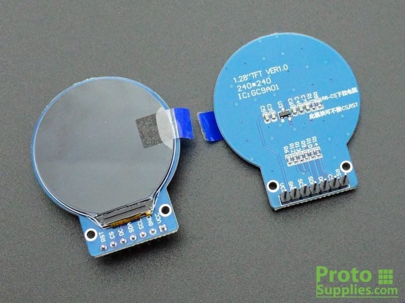
Pin order as printed on this exact board, top to bottom of the header (matches photo):
| Pin # | Name | Function | Notes |
|---|---|---|---|
| 1 | RST | Reset | Active LOW; must be pulsed/held per driver init sequence |
| 2 | CS | Chip Select | Active LOW |
| 3 | DC | Data/Command | LOW = command, HIGH = data |
| 4 | SDA | SPI MOSI | Data input to display; no MISO on this device |
| 5 | SCL | SPI Clock | |
| 6 | GND | Ground | |
| 7 | VCC | Power supply | 3.3–5V |
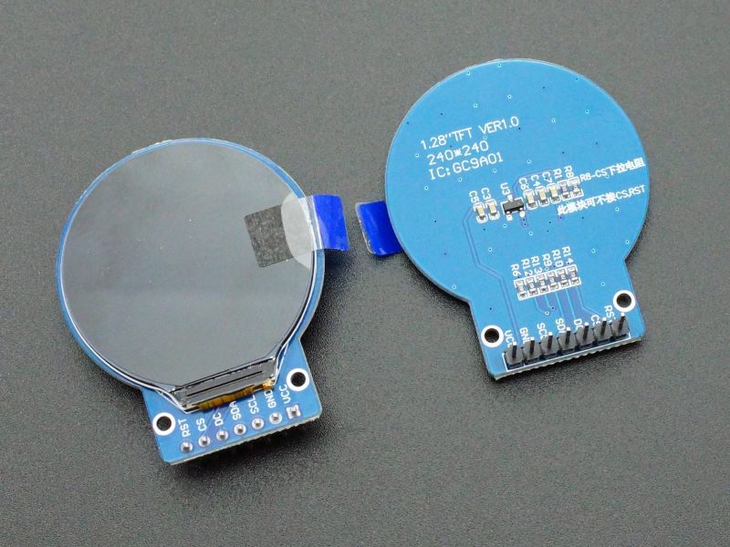
Note: this board’s silkscreen also shows unpopulated RB-CS/pull-resistor pads (R6, R8–R14, C3–C7) near the header — routing for CS pull and reset config. Not relevant to normal use; leave alone.
Wiring / typical usage
Standard 4-wire SPI: VCC/GND to power, SCL→SCK, SDA→MOSI, plus CS, DC, RST to any free GPIOs (not necessarily hardware SPI pins for CS/DC/RST — only SCL/SDA need the hardware SPI bus). Backlight is always on once VCC is applied — no PWM dimming without a hardware mod.
Code / libraries
- Recommended library (Arduino):
Adafruit_GC9A01A(best documented) or Waveshare’s sample code - Recommended library (ESP32 / PlatformIO):
TFT_eSPI(Bodmer) — widely used for this exact panel, supports GFX-style shapes/text - Config notes: set
TFT_WIDTH/TFT_HEIGHTto 240×240 and driver toGC9A01_DRIVERinUser_Setup.hfor TFT_eSPI; map CS/DC/RST/SCK/MOSI pins to whatever GPIOs are wired
Source material
- Datasheet: GC9A01 controller datasheet (Galaxycore) — not yet pulled locally
- Product page: this exact
M128-240240-RGB-7-V1.0board is unbranded/generic; closest documented equivalents:- https://protosupplies.com/product/ips-lcd-128-round-pcb-gc9a01/ (matches this 7-pin layout exactly)
- https://dronebotworkshop.com/gc9a01/ (8-pin variant with BLK, for comparison)
- Product photo:
/inventory/gc9a01-round-lcd-1.28in/product-photo.jpg— exact match (ProtoSupplies’ own photo of this same 7-pin board), sourced 2026-07-25 from https://protosupplies.com/wp-content/uploads/2022/11/TFT-LCD-1.28-240x240-Round-Display-GC9A01-Round-PCB.jpg - Purchase link: unknown (not recorded at time of intake)
- Local files: see
/inventory/gc9a01-round-lcd-1.28in/board-back.jpeg
Verification
Pinout labels (RST, CS, DC, SDA, SCL, GND, VCC) read directly off this board’s own silkscreen in the supplied photo — high confidence on names and order. Voltage/logic-level/current specs are Inferred from third-party vendor pages for the matching 7-pin GC9A01 board variant (ProtoSupplies, DroneBot Workshop) — not yet cross-checked against the GC9A01 IC datasheet itself. Confirm current draw and absolute max ratings against the datasheet before any tight power-budget design.
Notes / gotchas
- No touch layer — display only.
- No BLK pin on this variant — can’t dim backlight without modding the board (cutting the trace and pulling out a wire from the LED test pad, if present).
- Logic is 3.3V-only despite accepting 5V on VCC — don’t drive SCL/SDA/CS/DC/RST from a 5V MCU without level shifting.
- Round active area on a square-ish pixel buffer — most GFX libraries still address it as a 240×240 square framebuffer; corners are just unused/black.