LILYGO TTGO T-Display (ESP32, 1.14" LCD, CH9102F)
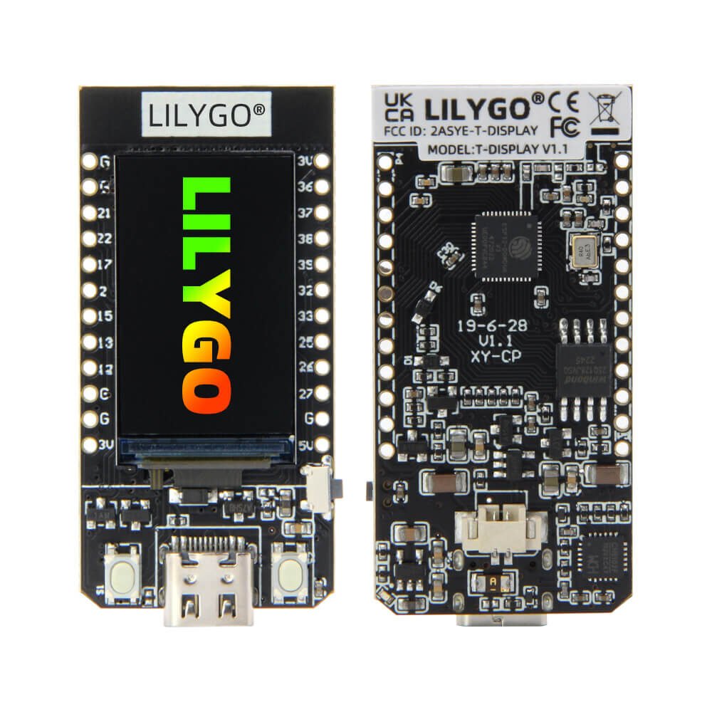
Overview
An ESP32 development board with a built-in 1.14“ IPS LCD (ST7789 driver, 135×240) soldered directly to the board — no wiring needed to get a screen running, unlike a bare ESP32 dev board paired with a separate display. WiFi + Bluetooth 4.2 (same ESP32 silicon as the Heltec WiFi LoRa 32 V4, no LoRa radio here though). USB-C via a CH9102F USB-to-UART chip (a CP2104/CH340-alternative — same board family also ships with those chips depending on batch, this unit is the CH9102F variant per its bag label).
Key specs
- MCU: ESP32 (240MHz dual-core LX6), WiFi 802.11 b/g/n + Bluetooth 4.2
- Flash: 16MB (per bag label) — QSPI, 4MB/16MB depending on SKU
- RAM: 520KB SRAM
- Display: 1.14“ IPS LCD, ST7789V driver, 135×240 resolution, 4-wire SPI, 3.3V
- USB: USB-C, CH9102F USB-to-UART bridge, up to 4Mbps
- Battery: 2-pin JST-SH (1.25mm pitch) connector, 3.0–4.2V input — same connector pitch as the Heltec V4 and NXD 103450 battery already in this library, worth a test-fit before assuming plug-and-play
- Power draw: ~60mA active, ~120µA deep sleep (typical for this board family)
- Two onboard buttons (unlabeled GPIO0/GPIO35 per LILYGO’s schematic — function depends on firmware, GPIO0 is also the boot-mode strap pin)
- Physical size: 51.52 × 25.04 × 8.54mm
Pinout
24-pin 2.54mm dual header (12 pins per side):
| Left header | GPIO | Right header | GPIO |
|---|---|---|---|
| GND | — | 3V3 | — |
| SDA | 21 | GPIO36/SVP | 36 (input-only ADC) |
| SCL | 22 | GPIO37 | 37 (input-only ADC) |
| GPIO17 | 17 | GPIO38 | 38 (input-only ADC) |
| GPIO2/T2 | 2 (strap) | GPIO39/SVN | 39 (input-only ADC) |
| GPIO15/T3 | 15 (strap) | GPIO32/T9 | 32 |
| GPIO13/T4 | 13 | GPIO33/T8 | 33 |
| GPIO12/T5 | 12 (strap) | GPIO25/DAC1 | 25 |
| GND | — | GPIO26/DAC2 | 26 |
| GND | — | GPIO27/T7 | 27 |
| 3V3 | — | GND | — |
| — | — | 5V/VIN | — |
Reserved for the onboard display (do not reassign):
| Function | GPIO |
|---|---|
| TFT_MOSI | 19 |
| TFT_SCLK | 18 |
| TFT_CS | 5 |
| TFT_DC | 16 |
| TFT_RST | 23 |
| TFT_BL (backlight) | 4 |
Battery monitoring: GPIO34 reads battery voltage through an onboard 1:2 divider (ADC1 channel 6); GPIO14 (ADC_EN) must be driven high to enable the divider before reading GPIO34.
Wiring / typical usage
Powers over USB-C for programming/power, or via the 2-pin JST-SH battery connector for portable use (onboard charge management, like the Heltec V4). The display is fully wired internally — just initialize it in software (see below) rather than wiring anything externally. GPIO0 and GPIO35 are the two onboard buttons; GPIO0 doubles as a strapping pin, so avoid driving it externally during boot.
Code / libraries
- Arduino: LILYGO’s own
TTGO-T-Displayboard support +TFT_eSPIlibrary (pre-configuredUser_Setup.hfor this exact board is in their GitHub repo) — select “ESP32 Dev Module” or the LilyGo-specific board entry, and setTFT_eSPIpins to match the table above if configuring manually. - Battery read: set GPIO14 HIGH,
analogRead(34), multiply by the divider ratio and ESP32 ADC reference to get actual voltage. - ESP-IDF / MicroPython: any ST7789 driver library works, using the SPI pin assignments above.
Source material
- Bag label (item code, manufacturer, USB chip variant, flash size) read directly from the supplied photo.
- Official specs, dimensions, and general pin table: LILYGO T-Display product page, espboards.dev pinout reference
- Display SPI pin assignments and battery ADC/enable pins: cross-referenced from the LilyGO
TTGO-T-DisplayGitHub repo’sTFT_eSPIexample configuration (widely mirrored across community docs). - Product photo:
/inventory/lilygo-ttgo-t-display-esp32/product-photo.jpg— genuine LILYGO official product photo (front + back), sourced 2026-07-25 from https://lilygo.cc/cdn/shop/files/LILYGO-T-DISPLAY_5_cd0e2152-00a0-4403-a557-f96f6ba0d1e4.jpg — pin labels in the photo were cross-checked against the pinout table above and match. - Local files: see
/inventory/lilygo-ttgo-t-display-esp32/as-supplied.jpeg(sealed bag with item label, as owned)

Verification
Bag label read directly from photo — high confidence on manufacturer/model/USB-chip/flash identity. Pinout table Verified against two independent official/community sources (LILYGO product page + espboards.dev + GitHub TFT_eSPI reference) that agree with each other and visually match the pin labels legible in LILYGO's own product photo. GPIO0/GPIO35 button function not independently confirmed against a schematic in this pass — treat as typical-for-family until checked against the official schematic if button behavior matters for a project.
Notes / gotchas
- GPIO4, 5, 16, 18, 19, 23 are committed to the display — don’t reassign them even though they’re not physically broken out on the edge headers.
- GPIO34/35/36/37/38/39 are input-only (no
pinMode(OUTPUT)) — standard ESP32 restriction, not specific to this board. - Same 1.25mm JST-SH battery pitch question as the Heltec V4 entry: don’t assume a 2.0mm JST-PH battery (like the NXD 103450) plugs in directly without a pitch check.
- Used in: Pocket Speaker — chosen over the ESP32-C3 SuperMini specifically because it has classic Bluetooth (BR/EDR), needed for A2DP audio streaming; the C3 is BLE-only.