Heltec WiFi LoRa 32 V4 (HTIT-WB32LAF)
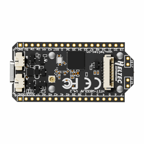
Overview
Heltec’s current-generation LoRa dev board: an ESP32-S3 paired with a Semtech SX1262 LoRa radio, a 0.96“ OLED, and onboard lithium battery + solar charge management, all on a 51.7×25.4mm module with a PC casing that integrates the 2.4G antenna. V4 is form-factor and pin-compatible with the earlier V3 board, but adds a solar panel input, a dedicated GNSS connector, gold-plated header pins, and (on this exact part number) a boosted 28dBm LoRa TX power option.
This specific unit is the HTIT-WB32LAF variant (no -N suffix) — the 28dBm high-power, 863–928MHz version, compatible with EU868/IN865/US915/AU915/AS923/KR920 regional plans. Lower-power sibling parts (-N-HF, -N-LF, -N-433) exist at 21dBm on different bands; this is not one of those.
Key specs
- Operating voltage: 5V via USB-C or 5V pin; 3.3–4.2V via lithium battery (JST SH1.25-2P)
- Logic level: 3.3V
- Current draw (active / sleep): WiFi scan ~119mA, LoRa TX @27dBm ~750mA (USB powered), RX ~75mA, sleep <20µA (battery or 3.3V-header powered), <2mA sleep when USB powered
- Interfaces: I2C ×2, SPI ×4, UART ×3, I2S ×2, 7×ADC1 + 2×ADC2, 7×Touch, PWM via GPIO matrix
- Clock speed / Flash / RAM: ESP32-S3R2 (dual-core Xtensa LX7) — 16MB external Flash, 2MB PSRAM, 512KB SRAM, 384KB ROM, 16KB RTC SRAM
- Wireless radios: Wi-Fi 802.11 b/g/n (≤150Mbps), Bluetooth LE 5 / Bluetooth mesh, LoRa via SX1262 (433
510MHz and 863928MHz bands supported by the chip; this board’s antenna/matching is tuned for the 863–928MHz high-power path)
Onboard peripherals: SSD1315-driven 0.96“ OLED (128×64), USB-C (with ESD/short-circuit/RF-isolation protection), 2× IPEX1.0 antenna connectors (LoRa + 2.4G), JST SH1.25-2P battery input, JST SH1.25-2P solar panel input, JST SH1.25-8P GNSS connector.
Pinout
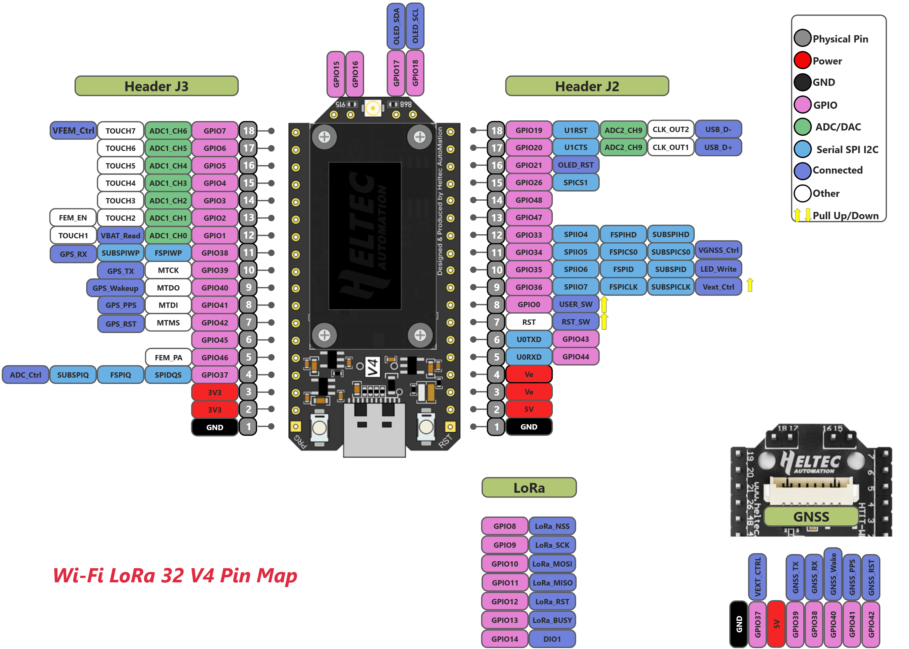
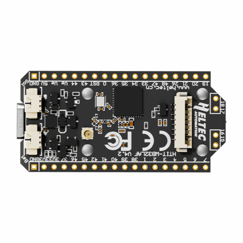
Two 18-pin headers (J2, J3) plus 4 additional broken-out pins. Numbering below matches the board’s own silkscreen (also visible in the supplied photo) and the official Heltec V4 pin map.
Header J2 (right side, pins 1–18 bottom-to-top in the photo):
| Pin # | Name | Function | Notes |
|---|---|---|---|
| 1 | GND | Ground | |
| 2 | 5V | 5V power supply | |
| 3 | Ve | 3.3V output | |
| 4 | Ve | 3.3V output | |
| 5 | RX (GPIO44) | U0RXD | |
| 6 | TX (GPIO43) | U0TXD | |
| 7 | RST | CHIP_PU / reset button | |
| 8 | 0 (GPIO0) | PRG button / boot select | |
| 9 | 36 (GPIO36) | SPIIO7, FSPICLK, SUBSPICLK, Vext_Ctrl | |
| 10 | 35 (GPIO35) | SPIIO6, FSPID, SUBSPID, LED | |
| 11 | 34 (GPIO34) | SPIIO5, FSPICS0, SUBSPICS0 | |
| 12 | 33 (GPIO33) | SPIIO4, FSPIHD, SUBSPIHD | |
| 13 | 47 (GPIO47) | SPICLK_P_DIFF, SUBSPICLK_P_DIFF | |
| 14 | 48 (GPIO48) | SPICLK_N_DIFF, SUBSPICLK_N_DIFF | |
| 15 | 26 (GPIO26) | SPICS1 | |
| 16 | 21 (GPIO21) | RTC, OLED_RST | |
| 17 | 20 (GPIO20) | RTC, U1CTS, ADC2_CH9, USB_D+ | |
| 18 | 19 (GPIO19) | RTC, U1RTS, ADC2_CH8, USB_D- |
Header J3 (left side, pins 1–18 bottom-to-top in the photo):
| Pin # | Name | Function | Notes |
|---|---|---|---|
| 1 | GND | Ground | |
| 2 | 3V3 | 3.3V power supply | |
| 3 | 3V3 | 3.3V power supply | |
| 4 | 37 (GPIO37) | SPIDQS, FSPIQ, SUBSPIQ, ADC_Ctrl | |
| 5 | 46 (GPIO46) | ||
| 6 | 45 (GPIO45) | ||
| 7 | 42 (GPIO42) | MTMS, GNSS_RST | |
| 8 | 41 (GPIO41) | MTDI, GNSS_PPS | |
| 9 | 40 (GPIO40) | MTDO, GNSS_Wakeup | |
| 10 | 39 (GPIO39) | MTCK, GNSS_TX | |
| 11 | 38 (GPIO38) | FSPIWP, SUBSPIWP, GNSS_RX | |
| 12 | 1 (GPIO1) | RTC, ADC1_CH0, TOUCH1, VBAT_Read | Battery voltage sense — see note below |
| 13 | 2 (GPIO2) | RTC, ADC1_CH1, TOUCH2 | |
| 14 | 3 (GPIO3) | RTC, ADC1_CH2, TOUCH3 | |
| 15 | 4 (GPIO4) | RTC, ADC1_CH3, TOUCH4 | |
| 16 | 5 (GPIO5) | RTC, ADC1_CH4, TOUCH5 | |
| 17 | 6 (GPIO6) | RTC, ADC1_CH5, TOUCH6 | |
| 18 | 7 (GPIO7) | RTC, ADC1_CH6, TOUCH7, VFEM_Control |
Additional broken-out pins (top of board, between the two headers):
| Name | Function | Notes |
|---|---|---|
| GPIO15 | XTAL_32K_P | |
| GPIO16 | XTAL_32K_N | |
| GPIO17 | OLED_SDA | Dedicated onboard OLED I2C — shared bus, don’t reuse for other I2C devices unless addressing allows |
| GPIO18 | OLED_SCL | Dedicated onboard OLED I2C |
GNSS connector (JST SH1.25-8P, right edge of board): GND, 3V3, GPIO39 (GNSS_TX), GPIO38 (GNSS_RX), GPIO40 (GNSS_Wake), GPIO41 (GNSS_PPS), GPIO42 (GNSS_RST), GPIO34 (VGNSS_Ctrl).
Battery voltage sense: GPIO1/ADC1_CH0 reads lithium battery voltage, but only when ADC_Ctrl (GPIO37, header J3 pin 4) is pulled HIGH first. Formula: VBAT = 100/(100+390) * V_ADC_IN.
LoRa (SX1262) internal SPI: GPIO8 (NSS), GPIO9 (SCK), GPIO10 (MOSI), GPIO11 (MISO), GPIO12 (RST), GPIO13 (BUSY), GPIO14 (DIO1) — these connect the ESP32-S3 to the onboard SX1262 radio internally; not broken out to headers, no manual wiring needed, just reference for library config.
Two 2-pin JST SH1.25 connectors on the left edge (visible in photo, labeled “SOL” and “BAT” on silkscreen): solar panel input and lithium battery input respectively.
Wiring / typical usage
This is a complete dev board, not a bare module — power via USB-C for development, or battery/solar for field deployment (both can be connected simultaneously alongside USB/5V input, per datasheet §3.2, but USB and the 5V pin must not be connected at the same time). OLED, LoRa radio, and antenna are all onboard and pre-wired — no external wiring needed to get LoRa + display running. GPIO0 is the boot-mode strap (hold low to enter download mode, same as any ESP32); RST is the hardware reset button. Battery charging draws up to 500mA from USB @5V.
Code / libraries
- Recommended library (Arduino): Heltec’s own
Heltec ESP32 Dev-Boardsboard package (Arduino IDE Boards Manager) — select “WiFi LoRa 32(V4)” or equivalent once V4 support lands in the package; check Heltec’s GitHub for current board-support status since V4 is a 2025 release. - LoRa radio library: RadioLib (actively maintained, SX126x support) is the common modern choice over Heltec’s older bundled LoRa library.
- Also directly compatible with Meshtastic (V3 was an officially supported Meshtastic board; V4 support should follow given pin/form-factor compatibility — confirm current Meshtastic device list before flashing).
- Config notes: OLED is SSD1315 (128×64) on a dedicated I2C bus at GPIO17 (SDA) / GPIO18 (SCL) — most SSD1306-compatible libraries (e.g.
Adafruit_SSD1306in SSD1306-compatible mode, or Heltec’s own OLED lib) work with this controller.
Source material
- Datasheet: official Heltec V4.2.0 datasheet — https://resource.heltec.cn/download/WiFi_LoRa_32_V4/datasheet/WiFi_LoRa_32_V4.2.0.pdf (local copy:
/inventory/heltec-wifi-lora-32-v4/heltec-official-pinmap.pngfor the pin map graphic; full datasheet PDF not saved locally, re-fetch from URL above if needed) - Official pin map (graphic): https://resource.heltec.cn/download/WiFi_LoRa_32_V4/Pinmap/V4_pinmap.png — saved locally at
/inventory/heltec-wifi-lora-32-v4/heltec-official-pinmap.png - Product page / wiki: https://wiki.heltec.org/docs/devices/open-source-hardware/esp32-series/lora-32/wifi-lora-32-v4/
- Product page: https://heltec.org/project/wifi-lora-32-v4/ (referenced via search; not independently fetched)
- Product photo:
/inventory/heltec-wifi-lora-32-v4/product-photo.png— exact match, official Heltec product photo, sourced 2026-07-25 from https://heltec.org/wp-content/uploads/2025/09/v4002-500x500.png - Purchase link: unknown (not recorded at time of intake)
- Local files: see
/inventory/heltec-wifi-lora-32-v4/board-back.jpeg(as-supplied photo),/inventory/heltec-wifi-lora-32-v4/heltec-official-pinmap.png(official Heltec pin map)
Verification
Verified against official Heltec WiFi LoRa 32 V4 datasheet Rev1.4 (V4.2.0, Sep 2025) and the official V4 pin map graphic, both pulled directly from resource.heltec.cn. Part number, board revision (HTIT-WB32LAF V4.2), header layout, and all pin labels read off the supplied photo match the official pin map exactly — header pin counts (18+18), silkscreen numbering, and connector positions (2× JST battery/solar on left, GNSS JST + antenna on right) all line up. High confidence on all specs above.
One inference: the exact TX-power/frequency sub-variant (HTIT-WB32LAF vs. the -N low-power siblings) is read from the silkscreen text alone (no -N suffix visible) — this determines the 28dBm/863-928MHz spec. If the board ever needs re-verification, check the silkscreen text under magnification for any suffix.
Notes / gotchas
- Don’t power via both USB-C and the 5V pin simultaneously — datasheet explicitly calls out only one 5V source at a time (battery/solar can coexist with either).
- GPIO1 battery-voltage read requires pulling GPIO37 (ADC_Ctrl) high first, or you’ll get a floating/incorrect reading.
- OLED I2C bus (GPIO17/18) is dedicated to the onboard display — if you need a second I2C device, either share this bus (check address conflicts) or use the second I2C peripheral on different GPIOs.
- This is the high-power (28dBm) variant — that draws up to ~750mA at max TX power on USB; budget accordingly if running off battery or a marginal USB supply.
- V4 is a very recent release (first official version dated Sep 2025) — third-party library/framework support (Arduino board package, Meshtastic, RadioLib board defs) may lag behind V3; confirm current support status before assuming a V3 example will “just work.”
- Each of the 4 units owned came bundled with a matching Heltec L76K GNSS module (drop-in fit for the onboard GNSS connector) — see
components/sensors/quectel-l76k-gnss/. - Alex also has a NXD 103450 LiPo battery and a YT Ø80mm round solar panel intended for this board’s
BAT/SOLinputs — connector pitch (1.25mm JST-SH on this board) is not yet confirmed against either part, flagged in both of their component docs. Verify by physical test-fit before assuming plug-and-play.