Unbranded DC-DC Converter Module (Dual 220µF/50V, Unmarked IC)
Overview
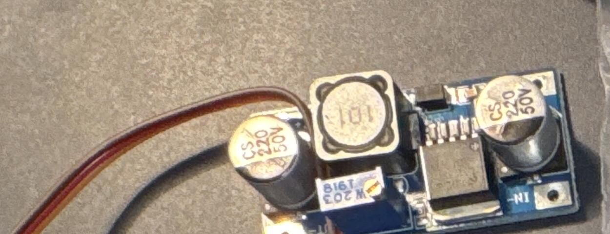
A small blue DC-DC converter board of unconfirmed topology (boost vs. buck) — the single-inductor, dual-large-capacitor layout is consistent with either, and the driver IC’s part number couldn’t be read from the supplied photo. Given the 50V-rated caps, this board is built for a meaningfully higher voltage range than typical 5V logic-level converters (e.g. the Dorhea MT3608 also in this library, which uses 25V caps) — worth measuring input/output behavior with a bench supply before assuming it behaves like a standard low-voltage boost module.
Key specs
- Capacitors: 2× 220µF, 50V electrolytic (input and output filtering, typical for this topology)
- Inductor: 1× large SMD power inductor, marked
101(this coding usually denotes inductance in µH using the same two-significant-figures-plus-multiplier scheme as resistor/capacitor codes —101= 10 × 10¹ = 100µH, though this convention isn’t universal across inductor manufacturers and isn’t confirmed for this specific part) - IC: 8-pin power conversion IC, marking not legible in the supplied photo (shadow/reflection obscured it)
- At least one labeled pad:
IN-(negative input terminal) - No visible adjustment potentiometer — likely a fixed-ratio or fixed-feedback-resistor design rather than user-adjustable output
Pinout
| Pad | Function |
|---|---|
| IN- | Input negative/ground |
| (unlabeled, opposite side) | Likely IN+ / OUT+ / OUT- — not confirmed from the photo |
Wiring / typical usage
Do not use this board until the topology and voltage ratings are confirmed — with an unidentified IC and 50V-rated caps, assuming it’s a simple 5V-range boost/buck converter could be wrong in either direction (higher max input than typical hobby boards, or a different regulation scheme entirely). Before wiring into any project, identify the IC (try reading the marking under better lighting/magnification, or via a continuity/behavior test with a bench supply at low voltage first) and confirm input/output voltage range with a multimeter rather than assuming.
Code / libraries
N/A — passive power hardware, no firmware interface.
Source material
- All specs read directly from physical inspection of the supplied photo (cap ratings, inductor marking, pad label) — the IC itself could not be identified this way.
- Product photo:
/inventory/unbranded-dcdc-boost-buck-converter/product-photo.jpg— the actual owned unit.
Verification
Capacitor and inductor markings read directly from the photo — high confidence on those two components only. Everything else (IC identity, exact topology, voltage/current ratings) is UNCONFIRMED — the driver IC's marking was illegible in the supplied photo. Do not assume boost vs. buck, or any specific voltage/current rating, without either reading the IC marking under better lighting or testing behavior directly with a bench supply.
Notes / gotchas
- Unidentified IC — treat with more caution than a typical hobby power module. Confirm behavior before connecting to anything valuable.
- 50V-rated caps suggest this board may be designed for a higher voltage range than the 5V-class converters elsewhere in this library — don’t assume it’s interchangeable with the MT3608 boost modules.
- Revisit this entry once the IC marking is read clearly (try a macro photo or magnifying glass) — update Verification and Key specs once confirmed.