Dorhea MT3608 DC-DC Step-Up (Boost) Converter Module
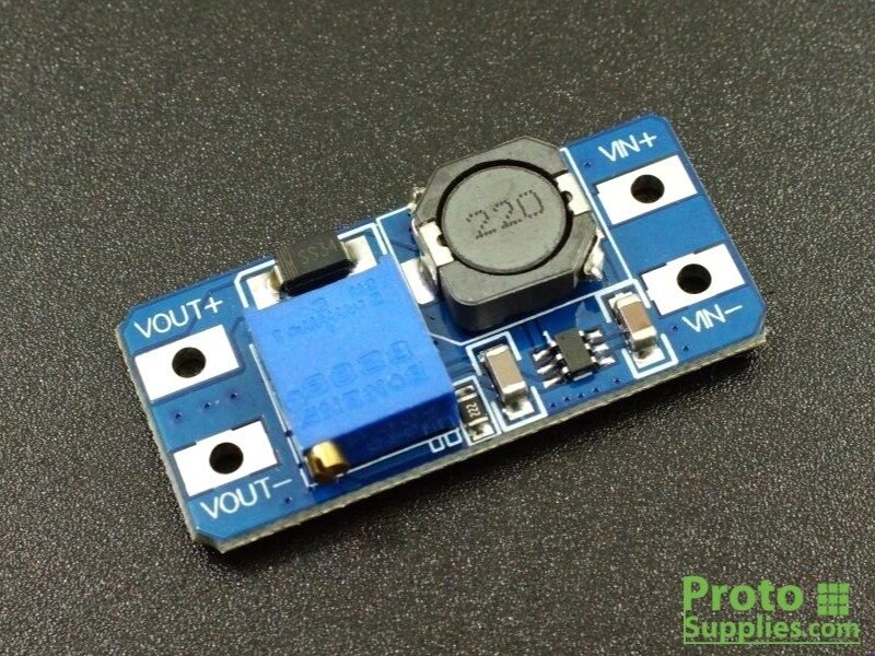
Overview
A small adjustable boost (step-up) converter board built around the MT3608 IC — takes a lower DC input voltage and steps it up to a higher, adjustable output via an onboard potentiometer. Common use case in this library’s context: boosting a single Li-ion/LiPo cell (~3.0–4.2V) up to 5V for powering 5V-logic peripherals, or up to higher voltages for other projects. Not a charger — this is one-directional step-up only, distinct from the buck-boost charging circuitry built into boards like the Heltec V4 or Pico 2 W.
Key specs
- Input voltage: 2–24V DC
- Output voltage: 5–28V DC, adjustable via onboard potentiometer
- Maximum output current: 2A
- Switching frequency: 1.2MHz
- Efficiency: ~93–97% depending on load/conditions
- Output ripple: <100mV (typical)
- Protections: under-voltage lockout, current limiting, thermal overload (per MT3608 IC spec)
- Dimensions: approx. 37.2 × 17.2 × 14.0mm
Pinout
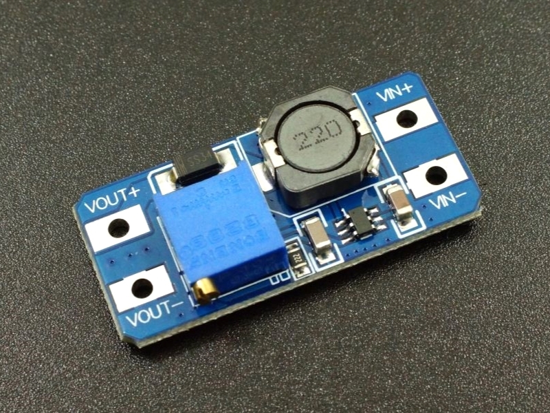
4-pin module, silkscreened on the board:
| Pin | Name | Function |
|---|---|---|
| 1 | VIN+ | Voltage input, positive |
| 2 | VIN− | Voltage input, ground |
| 3 | VOUT+ | Voltage output, positive (adjustable) |
| 4 | VOUT− | Voltage output, ground |
Wiring / typical usage
Input on VIN+/VIN−, output on VOUT+/VOUT− — input and output grounds are common (not isolated). Adjust the onboard potentiometer to the target output voltage before connecting a load — measure VOUT with a multimeter while turning the pot (commonly needs many turns, ~20+, to sweep the full range) rather than guessing a turn count. Per the IC’s boost topology, output voltage must always be set higher than the input voltage — this can’t be used to step down. Given the 2A max rating, check actual current draw of whatever’s downstream before relying on it near that ceiling; boost converters lose current headroom as the input/output voltage gap widens (input current draw increases roughly proportionally to the step-up ratio).
Code / libraries
N/A — passive analog power module, no digital interface.
Source material
- Dorhea listing (10-pack, 2A, matches quantity ordered): https://www.amazon.com/MT3608-Converter-Adjustable-Voltage-Regulator/dp/B0BGLGL9RV
- MT3608 module reference (pinout, specs, potentiometer adjustment procedure): https://components101.com/modules/mt3608-2a-dc-dc-step-up-power-module
- Local files: see
/inventory/dorhea-mt3608-boost-converter/amazon-order-list.jpeg(as-supplied order-history screenshot) - Product photo:
/inventory/dorhea-mt3608-boost-converter/product-photo.jpg— exact match, generic MT3608 module design (identical VIN/VOUT layout), sourced 2026-07-25 from https://protosupplies.com/wp-content/uploads/2019/06/MT3608-DC-DC-Boost-Converter.jpg
Verification
Verified against multiple independent third-party module references (components101.com and others) which agree on pinout and specs — this is an extremely common, well-documented module design. Not verified against a photo of the specific owned units’ own silkscreen, but the MT3608 boost module design is highly standardized across resellers (same 4-pin VIN/VOUT layout, same potentiometer placement) — high confidence despite no direct photo.
Notes / gotchas
- Set the output voltage before connecting any load — an unset or wrongly-set potentiometer can feed a downstream board far more voltage than expected, risking damage. Always verify with a multimeter first.
- Boost-only — cannot step voltage down. If a project needs both directions (e.g. an unpredictable input that sometimes exceeds the target), a buck-boost module is needed instead, not this one.
- Shared input/output ground — not isolated, keep that in mind for any circuit where ground isolation matters.