Pimoroni Tiny 2350
Overview
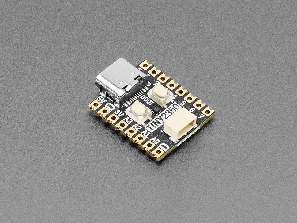
A tiny RP2350-based dev board in Pimoroni’s “Tiny” form factor (successor to the RP2040-based Tiny 2040) — USB-C, a STEMMA QT/Qwiic I2C connector, a programmable RGB LED, and a user-assignable BOOT button, all on a board small enough to disappear inside a project. No onboard display, IMU, or battery management, unlike the Waveshare RP2350-LCD-1.28 also in this library — this is a bare, general-purpose RP2350 board.
Key specs
- MCU: RP2350A, dual-core Arm Cortex-M33, up to 150MHz
- Flash: 4MB QSPI (XiP-capable); RAM: 520KB SRAM
- USB: USB-C (power, programming, data)
- GPIO: 12 general-purpose IO total (GP0–7 plus GP26–29), 4 of which are 12-bit ADC-capable (A0–A3)
- Interfaces: STEMMA QT/Qwiic I2C connector (fixed to GP12/GP13), PWM-capable RGB LED, PWM broadly available on the general-purpose pins
- Onboard: programmable RGB LED (GP18/19/20, active-low), RESET button, BOOT button (also wired as a user-readable switch on GP23, active-low), onboard 3.3V regulator (300mA max)
- Power input: 3V–5.5V via USB-C or header VBUS
- Dimensions: ~22.9 × 18 × 5.8mm (L×W×H, including the USB-C port) — matches Alex’s own measurement of “approximately 22 by 18mm” on the physical unit
Pinout
GPIO-to-function mapping sourced from Adafruit’s official CircuitPython board definition for this exact board (pimoroni_tiny2350) — an independent, authoritative source (actual pin-binding source code, not a secondary description).
| GPIO | Function | Reserved? |
|---|---|---|
| GP0–GP7 | General purpose | Free (8 pins) |
| GP12 | SDA — STEMMA QT/Qwiic I2C data |
Reserved |
| GP13 | SCL — STEMMA QT/Qwiic I2C clock |
Reserved |
| GP18 | LED_R — RGB LED red channel, active-low |
Reserved |
| GP19 | LED_G — RGB LED green channel, active-low |
Reserved |
| GP20 | LED_B — RGB LED blue channel, active-low |
Reserved |
| GP23 | USER_SW/BUTTON — BOOT button, also user-readable, active-low |
Reserved |
| GP26 / A0 | General purpose, ADC-capable | Free |
| GP27 / A1 | General purpose, ADC-capable | Free |
| GP28 / A2 | General purpose, ADC-capable | Free |
| GP29 / A3 | General purpose, ADC-capable | Free |
12 GPIO genuinely free for general use (GP0–7, GP26–29) — matches the “twelve IO pins total” spec from Pimoroni/Adafruit’s own listings exactly, a good cross-check on this pin table’s accuracy.
Physical header layout not independently confirmed: Pimoroni publishes an official pinout diagram PDF, but it’s image-based (not text-extractable) and wasn’t readable in this pass. The GPIO-to-function table above is solid (sourced from CircuitPython’s actual pin bindings), but which physical pin position on the header corresponds to each GPIO number, and where power/ground pins (3V3 out, VBUS, GND) physically sit, is not confirmed here — cross-check against the board’s own printed silkscreen (if legible) or Pimoroni’s PDF pinout diagram directly before soldering.
| Feature | Notes |
|---|---|
| STEMMA QT / Qwiic connector | I2C on GP12 (SDA) / GP13 (SCL) |
| RGB LED | GP18/19/20, active-low, PWM-dimmable per channel |
| BOOT / user button | GP23, active-low, doubles as a normal user-readable switch after boot |
| RESET button | Hardware reset, not a GPIO |
| General-purpose header | 12 of the board’s GPIO free for project use |
Wiring / typical usage
Power and program over USB-C — no separate battery management on this board (unlike the RP2350-LCD-1.28), so a portable build needs its own external charge/boost circuit if battery-powered. The STEMMA QT connector gives solder-free I2C sensor/display hookups (4-pin JST-SH 1mm pitch, Adafruit’s standard STEMMA QT connector — same ecosystem as SparkFun’s Qwiic). The BOOT button can be read as a normal input in software after boot (GP23, active-low) in addition to its usual boot-mode-select role.
Code / libraries
- Arduino:
arduino-pico(earlephilhower) board package, same as any RP2350 board — select the matching Pimoroni/generic RP2350 target once available, or a generic RP2350 board definition. - CircuitPython: official Adafruit-maintained board definition (
pimoroni_tiny2350) — download directly from circuitpython.org. - MicroPython: standard RP2350 UF2 builds work; Pimoroni also publishes their own MicroPython fork with extra board-specific helpers (RGB LED, etc.) — check Pimoroni’s GitHub before assuming the vanilla build covers the LED/button helpers.
Source material
- Dimensions, MCU, flash/RAM, USB, power specs, onboard features: Adafruit product page (#6248), Pimoroni official shop page — both independently fetched and in agreement.
- Full GPIO pin map (every reserved function): Adafruit CircuitPython
pins.cforpimoroni_tiny2350— authoritative source code, not a secondary description. - Official pinout diagram (image-based PDF, not text-extractable in this pass): Pimoroni Tiny 2350 pinout PDF via Core Electronics
- Product photo:
/inventory/pimoroni-tiny2350/product-photo.jpg— official Adafruit product photo, sourced 2026-07-26 fromhttps://cdn-shop.adafruit.com/970x728/6248-00.jpg. Representative, not a photo of the actual owned unit — no photo of Alex’s physical board was supplied for this intake; identification is based on Alex’s direct measurement (~22×18mm) matching Pimoroni’s published ~22.9×18mm dimension almost exactly, combined with the board being an RP2350-family product sold via Adafruit (consistent with therp2350ada2reference Alex provided). High confidence on identity, but flagged per this library’s standing convention for any component logged without a photo of the physical unit.
Verification
MCU, flash/RAM, USB, power, and onboard-feature specs verified against two independent official sources (Adafruit's own product page and Pimoroni's own shop page), which agree with each other. Full GPIO pin map sourced from Adafruit's official CircuitPython pin-binding source code — high confidence, and internally cross-checked (12 free GPIO in the table matches the "twelve IO pins total" spec exactly). Physical header pin position/ordering and the exact location of power/ground pins NOT confirmed — the official Pimoroni pinout PDF is image-based and wasn't text-extractable in this pass. Consult that PDF directly (or the board's own silkscreen) before wiring anything. Board identity itself is inferred, not photo-confirmed — no picture of the owned unit was available; matched instead by physical dimension (~22×18mm measured by Alex vs. ~22.9×18mm published) and the rp2350ada2 search term Alex supplied, which strongly points to this Adafruit-listed Pimoroni board. Treat as high-confidence but not certain until a photo or direct part-marking confirmation is available.
Notes / gotchas
- No onboard battery/charge management, no display, no IMU — unlike the RP2350-LCD-1.28, this is a bare general-purpose board; any portable/display project needs external parts for those.
- RGB LED and BOOT/user button are both active-low (per the sourced pin bindings) — a naive “HIGH = on” assumption will be inverted.
- GP12/13 are committed to the STEMMA QT connector — don’t reassign them for a second I2C bus or generic GPIO use without accounting for whatever’s plugged into that connector.
- Physical header layout (pin order, power/ground positions) is the one real gap in this entry — resolve against Pimoroni’s own pinout PDF or the board’s silkscreen before wiring, not this doc alone.
- Logged without a photo of the physical unit, per Alex’s request — flagged throughout rather than presented as fully photo-verified. Revisit if/when a photo becomes available.