0.96" I2C OLED Display Module (SSD1306-class)
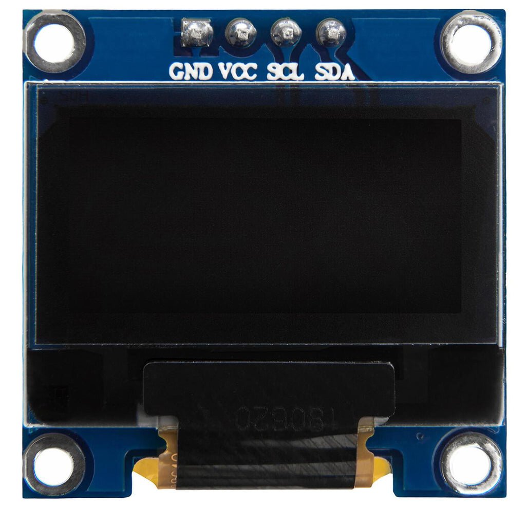
Overview
An assembled OLED breakout: a small blue driver PCB with an I2C address-select solder jumper (0x3C/0x3D, standard SSD1306 addressing) and a display panel attached via a folded FPC ribbon. Alex identified this as a .96“ display — consistent with the board’s I2C address-select layout, which is the common design for the 0.96“/128×64 SSD1306 OLED class (as opposed to the smaller 0.91“ bare panel also newly added to this library, which is 128×32 and unassembled).
Key specs
- Size: 0.96“ diagonal (per Alex’s identification)
- Typical for this class (128×64 SSD1306 OLED with I2C address-select jumper), consistent with the board’s own silkscreen but not cross-checked against a chip marking:
- Resolution: 128×64 pixels
- Driver IC: SSD1306
- Interface: I2C, 4-pin (GND, VCC, SCL, SDA)
- Default I2C address: 0x3C (jumper-selectable to 0x3D via the onboard solder pads, per silkscreen)
- Supply voltage: 3.3–5V typical for this breakout class (onboard charge-pump regulation is standard for SSD1306 modules)
Pinout
| Pin | Function |
|---|---|
| GND | Ground |
| VCC | Power (3.3–5V typical) |
| SCL | I2C clock |
| SDA | I2C data |
Exact pin order not confirmed from the photo (4-pin header partially obscured) — verify against the board’s own silkscreen labels before wiring, standard convention is GND-VCC-SCL-SDA but reseller boards occasionally reorder this.
Wiring / typical usage
Four wires to the host’s I2C bus: GND, VCC, SCL, SDA, same pattern as the 16x2 I2C LCD already in this library. Default address 0x3C should work out of the box; if a second SSD1306-class display is ever added to the same bus, use the 0x3D solder-jumper option on one of them to avoid an address collision.
Code / libraries
- Arduino:
Adafruit_SSD1306+Adafruit_GFX, initialize withdisplay.begin(SSD1306_SWITCHCAPVCC, 0x3C). - MicroPython:
ssd1306module (ssd1306.SSD1306_I2C(128, 64, i2c)), widely available. - If 0x3C doesn’t respond, run an I2C scanner before assuming the address jumper is set differently than expected.
Source material
- Board silkscreen (
IIC ADDRESS SELECT,0x3C/0x3Djumper pads) read directly from the supplied photo. - General 0.96“/128x64 SSD1306 I2C module class specs: UCTRONICS 0.96“ OLED module, Addicore SSD1306 0.96“ I2C OLED — generic class references, this exact reseller board not identified by brand.
- Product photo:
/inventory/oled-0.96in-i2c-module/product-photo.jpg— the actual owned unit (photo-verified silkscreen, address-select pads legible). - Local files: see
/inventory/oled-0.96in-i2c-module/as-supplied.jpeg
Verification
Board silkscreen (address-select jumper, FPC-mounted panel) read directly from the supplied photo — confirms this is an SSD1306-class I2C OLED breakout design, high confidence. Exact resolution (128×64) and pin order are Inferred from the well-documented 0.96" SSD1306 module class — not independently confirmed by a chip marking or datasheet lookup for this specific unbranded board. Run an I2C scanner and check the actual displayed resolution on first use rather than assuming 128x64 sight unseen.
Notes / gotchas
- No brand or model number anywhere on the board — if it ever needs replacing, match by the address-select jumper layout and FPC-mounted panel style rather than a specific part number.
- Distinct from the 0.91“ bare panel also in this library — that one is smaller (128×32), unassembled, and has no driver PCB at all.