GY-271 3-Axis Magnetometer / Digital Compass Module
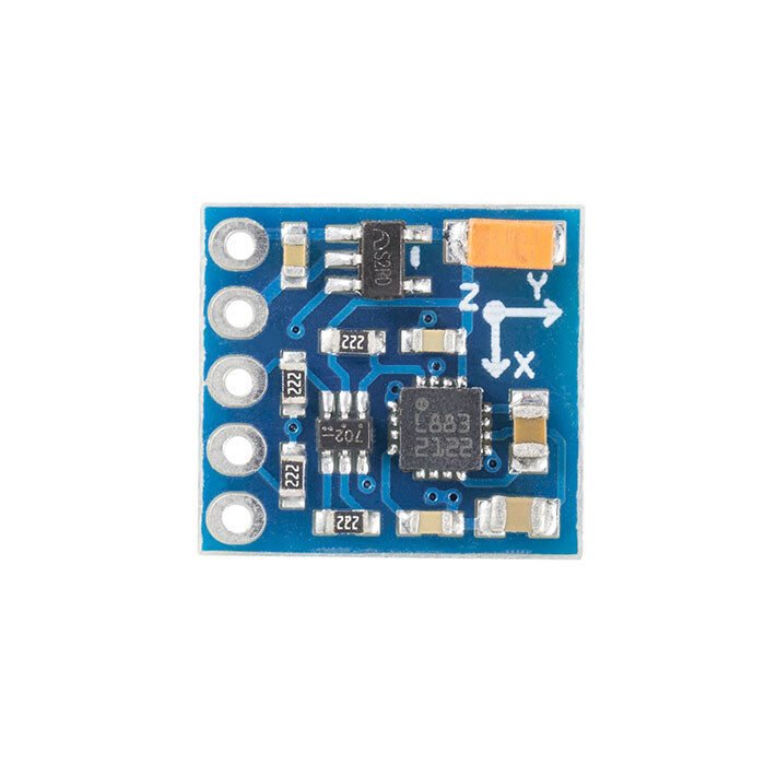
Overview
A small 3-axis magnetometer (digital compass) breakout board. Worth a correction on naming: Alex initially referred to this as a “gyroscope,” but GY-271 is actually a magnetometer — it senses magnetic field strength/direction (for compass heading), not angular velocity/rotation like a true gyroscope (e.g. the QMI8658 IMU on the Waveshare RP2350-LCD-1.28 also in this library does include a real gyroscope, alongside its accelerometer). 5 identical units owned.
Important sourcing note: the original Honeywell HMC5883L chip this board was designed around has been widely discontinued/counterfeited, and most GY-271 boards sold today (especially recent, cheap ones) actually ship with a QMC5883L clone chip instead — same board silkscreen and pin layout, but a different register map and address, requiring a different driver library. Which chip is actually on these 5 owned units was not confirmed from the supplied photo (chip marking obscured by the anti-static bag) — still open, see Verification.
Key specs
- Interface: I2C
- Operating voltage: 3–5V (per pin label
VCC, board likely has onboard regulation to the chip’s native 3.3V) - Pins:
VCC,GND,SCL,SDA,DRDY(data-ready interrupt output) - Measuring range: ±1.3 to ±8 Gauss (HMC5883L datasheet figure — QMC5883L clones have a similar but not identical range)
- Heading accuracy: ~1-2° (typical for this sensor class)
Pinout
| Pin | Function |
|---|---|
| VCC | Power (3–5V) |
| GND | Ground |
| SCL | I2C clock |
| SDA | I2C data |
| DRDY | Data-ready interrupt (active low, per HMC5883L convention) |
Wiring / typical usage
Standard I2C wiring: VCC/GND to power, SCL/SDA to the host’s I2C bus (pull-ups if not already present). DRDY is optional — connect to a GPIO interrupt pin if polling isn’t desired, otherwise leave unconnected. Before writing code, confirm which chip is actually on the board — genuine HMC5883L uses I2C address 0x1E with one register map; QMC5883L clones use address 0x0D with a different register map and initialization sequence. Running an I2C scanner is the fastest way to tell them apart (0x1E vs 0x0D).
Code / libraries
- If genuine HMC5883L (address 0x1E): Adafruit’s
Adafruit_HMC5883_Unifiedor similar. - If QMC5883L clone (address 0x0D): a QMC5883L-specific library (e.g.
QMC5883LCompass) — do not use an HMC5883L library on a QMC5883L chip, the register maps are incompatible enough to give garbage readings or fail silently. - Run an I2C scanner sketch first on each of the 5 owned units to determine which library applies — don’t assume all units use the same chip even if bought together.
Source material
- Board silkscreen (
GY-271, pin labelsVCC GND SCL SDA DRDY) read directly from the supplied photo. - HMC5883L vs. QMC5883L clone situation: widely documented across hobbyist electronics sources as a known issue with GY-271-labeled boards specifically (the board design predates the chip’s discontinuation and was never renamed after cheaper clones took over).
- Product photo:
/inventory/gy-271-hmc5883l-magnetometer/product-photo.jpg— representative (a genuine-HMC5883L-chip example of the GY-271 board family showing the same 5-pin layout and Z/Y/X axis silkscreen; the owned units’ actual chip — HMC5883L or QMC5883L clone — was not visible through the anti-static bag), sourced 2026-07-25 from SunFounder’s product page. - Local files: see
/inventory/gy-271-hmc5883l-magnetometer/as-supplied.jpeg(sealed bags, pin labels legible, chip not visible)
Verification
Board identity (GY-271) and pin labels read directly from the supplied photo — high confidence. Chip identity (genuine HMC5883L vs. QMC5883L clone) is UNCONFIRMED — not visible through the anti-static packaging. Run an I2C scanner (0x1E = HMC5883L, 0x0D = QMC5883L) before writing any driver code, and update this entry once known. This is a magnetometer, not a gyroscope — corrected from Alex's initial framing; the GY-271 name and 5-pin VCC/GND/SCL/SDA/DRDY layout are unambiguous for this board family.
Notes / gotchas
- Not a gyroscope — it’s a compass/magnetometer. If a project genuinely needs angular velocity (gyroscope) sensing, look at the QMI8658 on the RP2350-LCD-1.28 instead.
- Check I2C address before coding — 0x1E vs 0x0D determines which library and register map to use; guessing wrong will silently produce nonsense readings rather than an obvious error.
- Magnetometers are sensitive to nearby ferrous metal and other magnetic fields (motors, speakers, other electronics) — mounting location matters for compass accuracy in a real build.
- 5 identical units owned — confirm each one’s chip independently rather than assuming they match.