Full-Size Solderless Breadboard (830 Tie-Point)
Overview
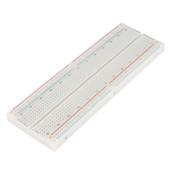
A standard full-size solderless breadboard: two terminal-strip blocks (columns 1–63, rows a–e and f–j) split by a central trough, flanked by two power-rail pairs (one per side, +/− marked in red/blue) running the board’s full length. This is the ubiquitous “830 tie-point” full-size layout used across nearly every breadboard-based tutorial and kit — no soldering needed, components and jumper wires push directly into the spring-clip holes.
Key specs
- Tie points: 830 (standard for this full-size layout — 630 terminal-strip points + 200 power-rail points; not independently counted on this unit, taken from the layout matching the well-known 830-point standard)
- Terminal strips: 2 blocks × 5 rows (a–e, f–j) × 63 columns, columns numbered 1–63 in groups of 5
- Power rails: 2 rails per side (+ and −, marked in red and blue respectively), running the full board length, electrically split from the terminal strip columns by design
- Hole pitch: 0.1in / 2.54mm (standard breadboard/DIP pitch)
- Construction: two joinable board sections (visible seam down the center), common on this size class so it can also be split into two half-size boards
- No brand markings anywhere on the board or the frame
Pinout
N/A — passive prototyping hardware, not a powered component. Standard breadboard electrical convention:
- Within a terminal-strip row (e.g.
a1–e1), all 5 holes are internally connected. - Terminal-strip columns are NOT connected across the center trough (
a–eside is isolated fromf–jside at the same column number). - Each power rail run (the full length of one +, or one −) is one continuous internal connection.
Wiring / typical usage
Standard breadboard prototyping: straddle the center trough with DIP ICs/modules so each pin lands in its own isolated row, use the side power rails for shared VCC/GND distribution, and jump between rows/rails with Dupont jumper wires. No current/voltage rating is printed on generic boards like this — spring-clip contacts are fine for typical low-current logic/sensor work (tens of mA per contact) but aren’t rated for motor-driver-level currents; route higher-current paths (e.g. to the 3V DC motor) through a proper connector or directly to the driver, not through long breadboard traces.
Code / libraries
N/A — passive prototyping hardware.
Source material
- Layout and tie-point count identified from the physical board itself (photo-verified column/row labeling, power rail placement) — matches the widely-documented generic “830 tie-point full-size breadboard” standard, e.g. SparkFun’s breadboard tutorial for the same layout convention.
- Product photo:
/inventory/full-size-solderless-breadboard/product-photo.jpg— the as-supplied photo is already a clean, well-lit shot of the actual unit; no separate manufacturer photo needed (board is unbranded regardless).
Verification
Layout (terminal strip / power rail arrangement, column numbering, row lettering) read directly from the physical board via photo — high confidence. Tie-point count (830) is the standard figure for this widely-used generic layout, not independently counted hole-by-hole on this specific unit.
Notes / gotchas
- No brand or model number anywhere on the unit — if it ever needs replacing, match by physical layout (2 terminal blocks + 2 power rail pairs, a–e/f–j lettering, 63 columns) rather than searching for a specific brand name.
- Center trough is exactly wide enough for standard 0.3in-wide DIP ICs to straddle without shorting rows — check part width before assuming any wider module fits both sides.
- Spring-clip contacts degrade with repeated insertions over years of reuse — if a connection seems flaky despite correct wiring, try a different hole in the same row before assuming the component or wire is bad.