Raspberry Pi Pico 2 W
Overview
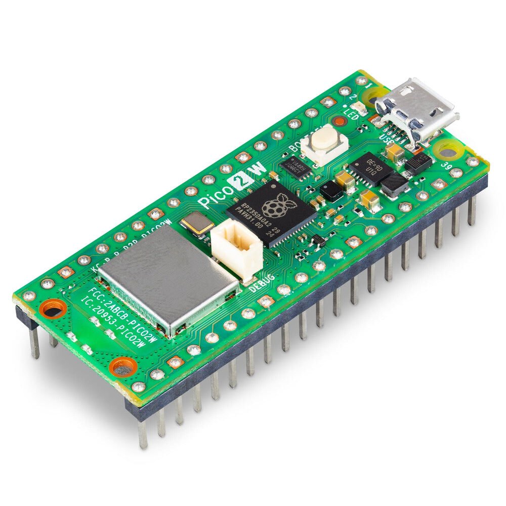
The wireless variant of Raspberry Pi’s second-generation Pico board: an RP2350 microcontroller (dual Cortex-M33 or dual RISC-V Hazard3 cores, switchable) paired with an Infineon CYW43439 for WiFi 4 + Bluetooth 5.2, in the same 21×51mm 40-pin DIP-style castellated footprint as the original Pico/Pico W. Alex identified this from a printed third-party pinout reference card (not a photo of the physical board), so intake here started from “part name known” rather than “photo of markings” — specs below are pulled from Raspberry Pi’s own datasheet rather than inferred from the card, though the card’s pin layout was cross-checked and matches.
Key specs
- Operating voltage: VSYS 1.8V–5.5V (onboard buck-boost SMPS regulates to 3.3V); VBUS (micro-USB) nominally 5V ±10%
- Logic level: 3.3V fixed on all GPIO (unlike the bare RP2350 chip, which can run I/O down to 1.8V — the Pico 2 W board hardwires it to 3.3V)
- Current draw: not tabulated in the datasheet in a single figure; ADC draws ~150µA extra when active; wireless/radio draw not specified locally — check RP2350 + CYW43439 datasheets directly if power-budgeting
- Interfaces: 2×UART, 2×I2C, 2×SPI, 16×PWM channels, 1×HSTX, 3×PIO blocks (12 state machines total, can bit-bang custom protocols e.g. SD card, VGA), 12-bit 500ksps ADC
- Clock speed / Flash / RAM: RP2350, dual-core (Cortex-M33 or RISC-V Hazard3, selectable) up to 150MHz; 520KB SRAM; flash size has a discrepancy in Raspberry Pi’s own datasheet — see Notes/gotchas
- Wireless radios: Infineon CYW43439 — WiFi 4 (802.11n, single-band 2.4GHz, WPA3, SoftAP up to 4 clients), Bluetooth 5.2 (LE Central/Peripheral + Bluetooth Classic), connected to the RP2350 via internal SPI (~33MHz), onboard Abracon/ProAnt “Niche” antenna
Pinout
26 of the RP2350’s 30 GPIO are broken out to the 40-pin header (GPIO0–22 digital-only; GPIO26–28 digital or ADC0–2). GPIO23–25 and GPIO29 are reserved internally for the wireless interface and VSYS/3 monitoring (ADC3) and are not on the header. Physical pin numbers below match both the official Raspberry Pi datasheet and the supplied reference card.
| Pin # | Name | Function | Notes |
|---|---|---|---|
| 1 | GP0 | UART0 TX, I2C0 SDA, SPI0 RX | |
| 2 | GP1 | UART0 RX, I2C0 SCL, SPI0 CSn | |
| 3 | GND | Ground | |
| 4 | GP2 | I2C1 SDA, SPI0 SCK | |
| 5 | GP3 | I2C1 SCL, SPI0 TX | |
| 6 | GP4 | UART1 TX, I2C0 SDA, SPI0 RX | |
| 7 | GP5 | UART1 RX, I2C0 SCL, SPI0 CSn | |
| 8 | GND | Ground | |
| 9 | GP6 | I2C1 SDA, SPI0 SCK | |
| 10 | GP7 | I2C1 SCL, SPI0 TX | |
| 11 | GP8 | UART1 TX, I2C0 SDA, SPI1 RX | |
| 12 | GP9 | UART1 RX, I2C0 SCL, SPI1 CSn | |
| 13 | GND | Ground | |
| 14 | GP10 | I2C1 SDA, SPI1 SCK | |
| 15 | GP11 | I2C1 SCL, SPI1 TX | |
| 16 | GP12 | UART0 TX, I2C0 SDA, SPI1 RX | |
| 17 | GP13 | UART0 RX, I2C0 SCL, SPI1 CSn | |
| 18 | GND | Ground | |
| 19 | GP14 | I2C1 SDA, SPI1 SCK | |
| 20 | GP15 | I2C1 SCL, SPI1 TX | |
| 21 | GP16 | SPI0 RX, I2C0 SDA, UART0 TX | |
| 22 | GP17 | SPI0 CSn, I2C0 SCL, UART0 RX | |
| 23 | GND | Ground | |
| 24 | GP18 | SPI0 SCK, I2C1 SDA | |
| 25 | GP19 | SPI0 TX, I2C1 SCL | |
| 26 | GP20 | I2C0 SDA | |
| 27 | GP21 | I2C0 SCL | |
| 28 | GND | Ground | |
| 29 | GP22 | General GPIO | |
| 30 | RUN | RP2350 enable/reset | Internal ~50kΩ pull-up to 3.3V; short low to reset |
| 31 | GP26 | ADC0, I2C1 SCL | |
| 32 | GP27 | ADC1, I2C1 SDA | |
| 33 | GND (AGND) | Analog ground | Separate analog ground plane for GPIO26–29 |
| 34 | GP28 | ADC2 | |
| 35 | ADC_VREF | ADC reference voltage | Filtered from 3.3V; can be driven externally for better ADC accuracy |
| 36 | 3V3(OUT) | 3.3V power output | Powers RP2350 + I/O; keep external load under 300mA |
| 37 | 3V3_EN | SMPS enable | Pulled high via 100kΩ; short to GND to disable 3.3V rail (powers down the whole board) |
| 38 | GND | Ground | |
| 39 | VSYS | Main system input voltage | 1.8–5.5V range, feeds the onboard buck-boost SMPS |
| 40 | VBUS | USB 5V input | From micro-USB pin 1; ~5V, 0V if USB unpowered |
Not on the header (internal use only): GPIO23 (wireless power-on), GPIO24 (wireless SPI data/IRQ), GPIO25 (wireless SPI CS), GPIO29 (wireless SPI CLK, doubles as ADC3 for VSYS/3 monitoring). On the CYW43439 side: WL_GPIO0 (drives the onboard user LED), WL_GPIO1 (controls SMPS power-save mode), WL_GPIO2 (VBUS-present sense).
Debug header (separate 3-pin): SWCLK, GND, SWDIO — standard Arm SWD, RP2350 has internal ~60kΩ pull-ups on both signal lines.
Six test points (SMT-module use, not normally needed): TP1 (GND), TP2 (USB D-), TP3 (USB D+), TP4 (SMPS PS pin — do not use externally), TP5 (WL_GPIO0/LED — not recommended for external use), TP6 (BOOTSEL — short low at power-up to force USB mass-storage programming mode, same effect as holding the BOOTSEL button).
Wiring / typical usage
Power via micro-USB for development (also enables USB mass-storage flashing by holding BOOTSEL at power-up). For battery use, feed VSYS directly (1.8–5.5V) — a single Li-ion cell or 3×AA in series both work without extra regulation, thanks to the onboard buck-boost SMPS. GPIO26–29 have a reverse protection diode to the 3.3V rail — don’t feed them more than ~300mV over 3.3V, and don’t apply voltage to them while the board is unpowered (it’ll leak into 3.3V through the diode); GPIO0–25 don’t have this restriction. RUN pin shorted to GND resets the chip in hardware.
Code / libraries
- Official SDKs: C/C++ SDK (
pico-sdk) or MicroPython — Raspberry Pi’s own “Getting started with Raspberry Pi Pico-series” book covers both. - Wireless stack (WiFi/Bluetooth) ships as part of the Pico SDK for the CYW43439 (
pico_cyw43_archin C/C++;networkmodule built into MicroPython builds targeting Pico 2 W). - Board target strings differ from the original Pico W — make sure build configs/board defs specifically target
pico2_w(RP2350), notpico_w(RP2040); they are not interchangeable despite similar names.
Source material
- Datasheet: official Raspberry Pi Pico 2 W Datasheet, Release 2, build date 03/07/2026 — https://datasheets.raspberrypi.com/picow/pico-2-w-datasheet.pdf (saved locally at
/inventory/raspberry-pi-pico-2-w/official-datasheet.pdf) - Local files: see
/inventory/raspberry-pi-pico-2-w/pinout-reference-card.jpeg(as-supplied printed reference card, third-party but datasheet-accurate),/inventory/raspberry-pi-pico-2-w/official-datasheet.pdf - Product photo:
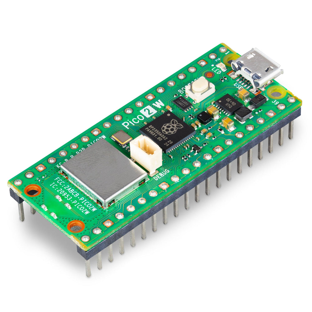
/inventory/raspberry-pi-pico-2-w/product-photo.jpg— exact match, official Raspberry Pi Pico 2 W board (The Pi Hut’s product photo), sourced 2026-07-25 from https://thepihut.com/cdn/shop/files/raspberry-pi-pico-2-w-raspberry-pi-sc1634-1146616007_1000x.jpg
Verification
Verified against the official Raspberry Pi Pico 2 W datasheet (Release 2, 03/07/2026), pulled directly from datasheets.raspberrypi.com. The supplied printed reference card’s pin layout, GPIO functions, and internal/wireless pin assignments all cross-check exactly against the official datasheet — high confidence on the full pinout table above. This entry started from a part name + third-party reference card rather than a photo of the physical unit’s markings, but the primary source used for every spec in this document is Raspberry Pi’s own datasheet, not the card.
Notes / gotchas
- Flash size discrepancy in Raspberry Pi’s own datasheet: the overview section states “RP2350 microcontroller with 4 MB of flash memory,” but §3.1 (“Programming the flash”) says “the on-board 2 MB QSPI flash can be (re)programmed…” and the components list names the flash chip as Winbond
W25Q16JV(a 16Mbit = 2MB part). Third-party listings (Adafruit, Seeed Studio) consistently state 4MB, and 4MB matches the expected “double the Pico W’s 2MB” positioning of the RP2350 generation — so 4MB is very likely correct and the “2MB”/W25Q16JVmentions are a copy-paste leftover from the original Pico W datasheet template. If flash partitioning ever matters for a project, check the actual flash chip marking on the physical board rather than trusting either figure blindly. - GPIO26–29 diode protection means these four pins are not 5V-tolerant and shouldn’t be probed while the board is powered off if the signal source is live.
- I/O is fixed at 3.3V on this board — the bare RP2350 chip itself supports down to 1.8V I/O, but that flexibility isn’t exposed here.
- Board target name matters: don’t reuse Pico W (RP2040) build configs, board files, or assume identical performance/RAM — this is a different, more capable chip in the same footprint.