KY-040 Rotary Encoder with Push Button + Knob Cap (QSYZAIL, 6pcs)
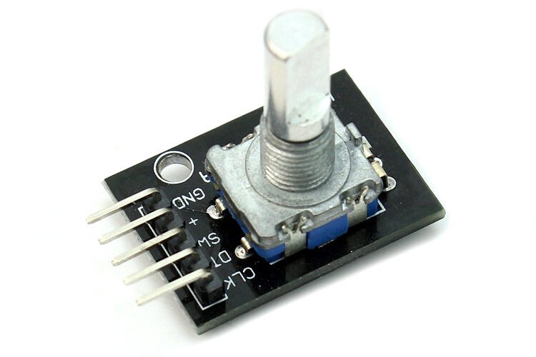
Overview
A breakout board for a mechanical incremental rotary encoder with an integrated momentary push-button (press the shaft to click). Widely used for menu navigation, volume/value adjustment, and any UI needing “turn to change, press to select” input. The board adds two 10kΩ pull-up resistors for the CLK/DT lines, so no external pull-ups are strictly required.
Key specs
- Operating voltage: 5V typical (also works at 3.3V logic, commonly used with ESP32/Pico)
- Logic level: matches supply (board pull-ups tie to VCC)
- Resolution: 20 pulses per rotation (detents)
- Output: 2-bit Gray code on CLK/DT (quadrature) for direction sensing
- Mechanical: 30mm × 18mm × 30mm module; operating temp -20°C to +70°C
Pinout
| Pin | Function |
|---|---|
| CLK | Encoder output A (quadrature) |
| DT | Encoder output B (quadrature) |
| SW | Push-button switch (momentary, active-low with board pull-up) |
| + (VCC) | Power |
| GND | Ground (shared — also the encoder’s common pin) |
Wiring / typical usage
Power the board from 3.3V or 5V. Wire CLK and DT to two GPIOs capable of interrupts (or fast polling) — direction is read by comparing the order CLK and DT toggle. Wire SW to a third GPIO with an internal pull-up enabled (or rely on the board’s own pull-up) — it reads low when pressed. No external pull-ups or debounce components are required, though firmware-side debounce is still good practice for both the detents and the button.
Code / libraries
- Arduino:
Encoderlibrary (PJRC) or a simple interrupt-based Gray-code state machine are both standard for this exact module. - ESP32/Pico (MicroPython/CircuitPython):
rotaryio.IncrementalEncoder(CircuitPython) reads CLK/DT directly; SW is a plain digital input. - Config notes: each detent (click-stop) typically produces one full quadrature cycle — expect ~20 steps per full rotation, matching the 20-pulse resolution.
Source material
- Datasheet/pinout: components101 KY-040 pinout/datasheet page
- Purchase link: Amazon, “QSYZAIL 6 Pcs KY-040 Rotary Encoder with Push Button and Knob Cap Compatible with for Arduino”
- Product photo:
/inventory/ky040-rotary-encoder/product-photo.jpg— components101’s KY-040 module photo. Representative of the standard KY-040 board layout (CLK/DT/SW/+/GND silkscreen matches the owned units per the purchase listing photo); not the exact QSYZAIL-branded unit.
Verification
Pinout and specs verified against components101's KY-040 writeup, cross-referenced against multiple KY-040 datasheet sources (Joy-IT, KEYES) — this is a highly standardized module design across resellers, high confidence.
Notes / gotchas
- “KY-040” is a generic module design manufactured/resold by many vendors under the same name and pin layout — expect near-identical wiring across brands.
- The push-button (SW) is a separate mechanical switch from the encoder’s rotation sensing — a “stuck” knob that won’t click is a different failure mode than one that clicks but doesn’t register turns.
- Knob caps included in this batch fit the encoder’s D-shaft; factor in their added height/diameter for panel-mount enclosure cutouts.