Soil Moisture Sensor — HW-080 Probe + HW-103 Comparator Module
Overview
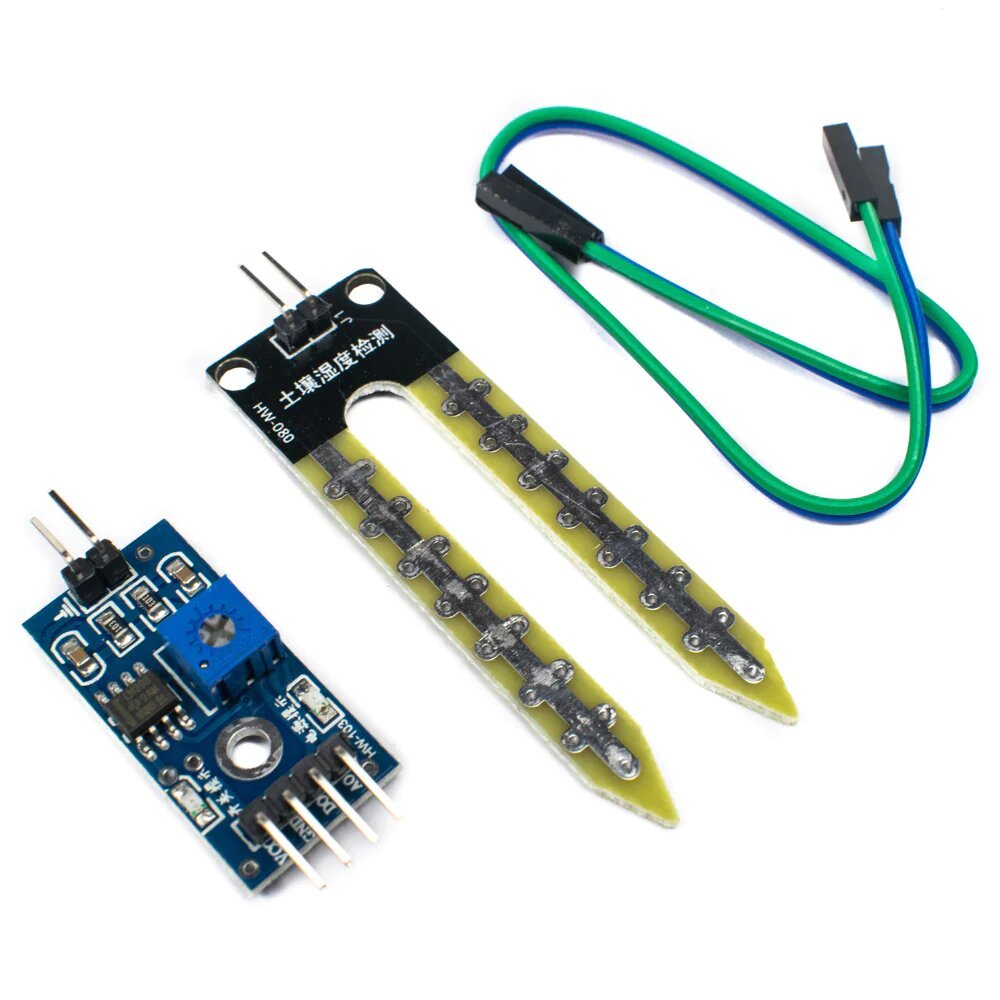
The common two-board Chinese soil moisture sensor kit: a forked PCB probe (HW-080) that gets pushed into soil, wired to a separate comparator/driver board (HW-103 V0.1.2) that conditions the probe’s raw resistance reading into both an analog voltage and a threshold-triggered digital signal. This is functionally the same design family as the more commonly-documented YL-69 (probe) + YL-38 (module) pair — same operating principle, different silkscreen branding. The probe and module connect via a 2-pin JST-XH-style connector (white housing, visible on both boards in the supplied photo).
Key specs
- Probe (
HW-080): two parallel nickel-plated PCB fork prongs, no active electronics — a simple variable resistor whose resistance drops as surrounding soil moisture (and thus conductivity) increases. 2-pin JST-style connector at the top. - Module (
HW-103 V0.1.2): LM393-style comparator IC, onboard potentiometer (blue, for digital-trigger threshold adjustment), power/status LEDs, 4-pin header (VCC, GND, DO, AO) plus a secondary 3-pin header/connector pointing to the probe side. - Operating voltage: 3.3V–5V DC (typical for this LM393-comparator module family)
- Operating current: ~15mA typical for this module family
- Outputs:
- AO (analog): variable voltage that tracks moisture level continuously — higher moisture generally reads as a lower resistance / different analog voltage, direction depends on the specific board’s driver circuit and should be confirmed empirically rather than assumed
- DO (digital): HIGH/LOW flip once the analog reading crosses the threshold set by the onboard potentiometer — useful for a simple “dry/not-dry” trigger without needing an ADC
Pinout
Module (HW-103) 4-pin header:
| Pin | Function |
|---|---|
| VCC | 3.3V–5V power |
| GND | Ground |
| DO | Digital output (threshold-triggered HIGH/LOW) |
| AO | Analog output (continuous voltage, needs an ADC-capable pin) |
Probe (HW-080) connector: 2-pin JST-style, wired directly to the module’s sense input (probe itself has no fixed polarity marking — the two prongs are electrically symmetric, a simple resistive path through the soil between them).
Wiring / typical usage
Connect the probe to the module via the supplied 2-pin connector (or matching wires if unplugged). Power the module’s VCC/GND from the host board’s 3.3V or 5V rail (whichever the host’s logic level and this module’s onboard regulation supports — not confirmed which this board expects, verify with a multimeter or start at 3.3V and check the output swing). Read AO on an ADC-capable pin for a continuous moisture value, or DO on any digital GPIO for a simple threshold trigger — adjust the potentiometer to set that threshold. Avoid leaving the probe powered continuously while inserted in soil for long periods; like most resistive soil probes, continuous current through the exposed traces accelerates electrolytic corrosion of the prongs — power it only when taking a reading if long-term deployment is the goal.
Code / libraries
- Arduino: read
AOwithanalogRead()on any analog-capable pin; readDOwithdigitalRead()on any digital pin. No dedicated library needed — this is a raw comparator/resistive sensor, not a digital/I2C part. - Calibration is empirical: take an
analogRead()reading with the probe fully dry (in air) and fully wet (in water or saturated soil) to establish the two ends of the range for this specific unit before trusting any absolute “percent moisture” figure.
Source material
- Board identities (
HW-080,HW-103 V0.1.2) read directly from silkscreen in the supplied photo — high confidence. - General pin function and operating spec cross-reference (this module family, VCC/GND/DO/AO 4-pin layout, LM393-based, 3.3–5V, ~15mA): Soil Moisture Sensor Module — components101.com
- Combined HW-080/HW-103 reference document (module description, found via a source literally filenamed for this exact pair): sitelec.org hw080_hw103 reference — page could not be fetched directly to extract text (redirect/download-gate issue), cited for future reference but not used to source any spec above.
- Product photo:
/inventory/hw080-hw103-soil-moisture-sensor/product-photo.jpg— the as-supplied photo is a clean, in-focus, well-lit shot of the actual probe and module; no separate manufacturer photo needed.
Verification
Board identities verified directly from silkscreen (HW-080, HW-103 V0.1.2) via photo — high confidence. Electrical specs (voltage range, current draw, pin functions) are Inferred from the well-documented generic LM393-comparator soil-sensor module family (same 4-pin VCC/GND/DO/AO layout as YL-38/HW-103-class boards) — not confirmed against a manufacturer datasheet for this specific silkscreen revision, since none is published for this generic part. Confirm actual voltage tolerance and output direction (does AO rise or fall with moisture) empirically before relying on either in code.
Notes / gotchas
- Two physically separate PCBs, connected by a small JST-style plug — don’t lose the interconnect if they ever get separated in storage; the module alone reads nothing without the probe attached.
- Probe prongs will corrode over time with repeated soil contact, especially if left powered continuously — treat reading drift over months as a symptom of prong corrosion, not necessarily a code or calibration bug.
- Threshold potentiometer only affects
DO— if usingAOfor a continuous reading, the potentiometer position doesn’t matter.