AITRIP ESP32-C3 Mini Development Board ("SuperMini")
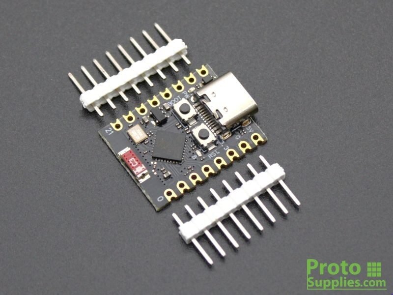
Overview
A tiny (22.5×18mm) ESP32-C3 breakout board following the widely-cloned “ESP32-C3 SuperMini” reference layout — single-core RISC-V, WiFi + Bluetooth LE, USB-C with native USB serial, 16-pin 2.54mm header (unpopulated pin headers ship separately, visible alongside the boards in the order photo). AITRIP is one of many resellers shipping this same board design. Alex supplied the listing’s own product-gallery photos (chip close-up, BOOT/RST button close-up, and an official pin-definition diagram), which confirmed the board and let the pinout below be corrected against the actual silkscreen rather than a generic third-party reference.
Key specs
- Operating voltage: 5V via USB-C, or 3.3V direct; onboard regulator accepts ~4.3–6.0V on the 5V pin
- Logic level: 3.3V only — not 5V tolerant, do not drive GPIO from a 5V source
- Current draw: not confirmed for this specific board
- Interfaces: UART, I2C, SPI (all via GPIO matrix — pins are software-assignable except where noted below), 13 PWM-capable GPIO
- Clock speed / Flash / RAM: ESP32-C3, single-core RISC-V @ 160MHz, 400KB SRAM, 4MB flash (QIO mode)
- Wireless radios: WiFi 802.11 b/g/n, Bluetooth 5.0 (BLE); antenna type not clearly identifiable from the supplied close-up photo (small board-edge antenna, could be a PCB trace or a small ceramic chip antenna) — not confirmed either way
Pinout
16-pin header, 2.54mm pitch. Physical left/right order below is read directly off this board’s own silkscreen (via the listing’s official pin-definition diagram) — corrected from an earlier draft of this doc that used a generic third-party pin order that didn’t match this board:
Left side (top to bottom, nearest USB-C):
| Name | Function | Notes |
|---|---|---|
| 5V | 5V power input | |
| G | Ground | |
| 3.3 | 3.3V power output | |
| GPIO4 | ADC1_CH4 (silkscreened A4), SPI SCK |
Strapping pin, JTAG |
| GPIO3 | ADC1_CH3 (silkscreened A3) |
|
| GPIO2 | ADC1_CH2 (silkscreened A2) |
Strapping pin |
| GPIO1 | ADC1_CH1 (silkscreened A1) |
|
| GPIO0 | ADC1_CH0 (silkscreened A0) |
Right side (top to bottom, nearest USB-C):
| Name | Function | Notes |
|---|---|---|
| GPIO5 | ADC2_CH0 (silkscreened A5), SPI MISO |
Strapping pin, JTAG |
| GPIO6 | SPI MOSI | Strapping pin, JTAG |
| GPIO7 | SPI SS | Strapping pin, JTAG |
| GPIO8 | I2C SDA | Strapping pin; also drives onboard status LED (inverted logic) |
| GPIO9 | I2C SCL | Strapping pin; also wired to the onboard BOOT button |
| GPIO10 | General GPIO | |
| GPIO20 | UART RX | |
| GPIO21 | UART TX |
Two additional buttons are on-board but not part of the 16-pin header: BOOT (also GPIO9, as noted above) and a separate RST hardware reset button — confirmed present in the listing’s close-up photo, correcting an earlier assumption in this doc that this board lacked a physical reset button.
Wiring / typical usage
Power and program over USB-C — the board enumerates as a native USB CDC serial device, no separate USB-UART chip needed. GPIO8 and GPIO9 do double duty (status LED / BOOT button respectively, on top of I2C SDA/SCL) — using I2C on this board means sharing those lines with the LED and boot-mode strapping, which is usually harmless after boot but worth knowing if I2C misbehaves specifically at power-up. GPIO4–7 are also JTAG pins — avoid them if debugging over JTAG is ever needed alongside their SPI use.
Code / libraries
- Standard ESP32 Arduino core or ESP-IDF both support ESP32-C3 — select an “ESP32C3 Dev Module” (or SuperMini-specific variant if the board manager offers one) as the board target.
- MicroPython: standard ESP32-C3 generic build works.
- Both BOOT and RST buttons are present on this board — standard boot-mode entry (hold BOOT, tap RST, release BOOT) works for manual flashing if auto-reset via USB CDC ever doesn’t trigger.
Source material
- AITRIP listing’s own product-gallery photos (chip close-up, BOOT/RST close-up, official pin-definition diagram) — supplied directly by Alex, saved locally at
/inventory/aitrip-esp32-c3-supermini/official-pin-diagram.png - AITRIP listing (2-pack, 4MB flash, matches quantity and flash size ordered): https://www.amazon.com/AITRIP-ESP32-C3-Development-Board-Bluetooth/dp/B0FBGDFPBQ
- Cross-reference (general SuperMini design background): https://lastminuteengineers.com/esp32-c3-super-mini-pinout-reference/ and https://www.espboards.dev/esp32/esp32-c3-super-mini/
- Local files: see
/inventory/aitrip-esp32-c3-supermini/amazon-order-list.jpeg(order-history screenshot),/inventory/aitrip-esp32-c3-supermini/official-pin-diagram.png(listing’s own pin definition diagram + chip/button close-ups) - Product photo:
/inventory/aitrip-esp32-c3-supermini/product-photo.jpg— representative (ProtoSupplies’ generic ESP32-C3 SuperMini reference-design board — same USB-C/dual-button layout, not AITRIP-branded specifically), sourced 2026-07-25 from https://protosupplies.com/wp-content/uploads/2025/01/ESP32-C3.jpg

Verification
Verified against the AITRIP listing's own product photos — chip marking (ESP32-C3), board silkscreen ("ESP32-C3 Super Mini"), BOOT/RST button placement, and an official pin-definition diagram specific to this board. This superseded an earlier draft of this doc that had used a generic third-party pin order and incorrectly assumed no RST button was present — both corrected here. Still not verified against a photo of Alex’s own physical units specifically (these are listing photos, not photos of the owned hardware), but this is now a board-specific, high-confidence source rather than a generic reference-design inference. Flash size (4MB) confirmed from the listing title and the order screenshot; quantity updated to 4 per Alex’s direct count (originally logged as 2 from the order screenshot alone).
Notes / gotchas
- Not 5V tolerant on GPIO — 3.3V logic only, unlike some 5V-tolerant boards in this library.
- GPIO8/9 sharing with LED/BOOT and GPIO4-7 sharing with JTAG are the two most likely sources of “weird” behavior if this board’s I2C or SPI acts up — check those overlaps first.
- Has both BOOT and RST buttons — don’t assume manual boot-mode entry requires a power cycle; the RST button handles it.