4-Channel 5V Relay Module (Songle SRD-05VDC-SL-C)
Overview
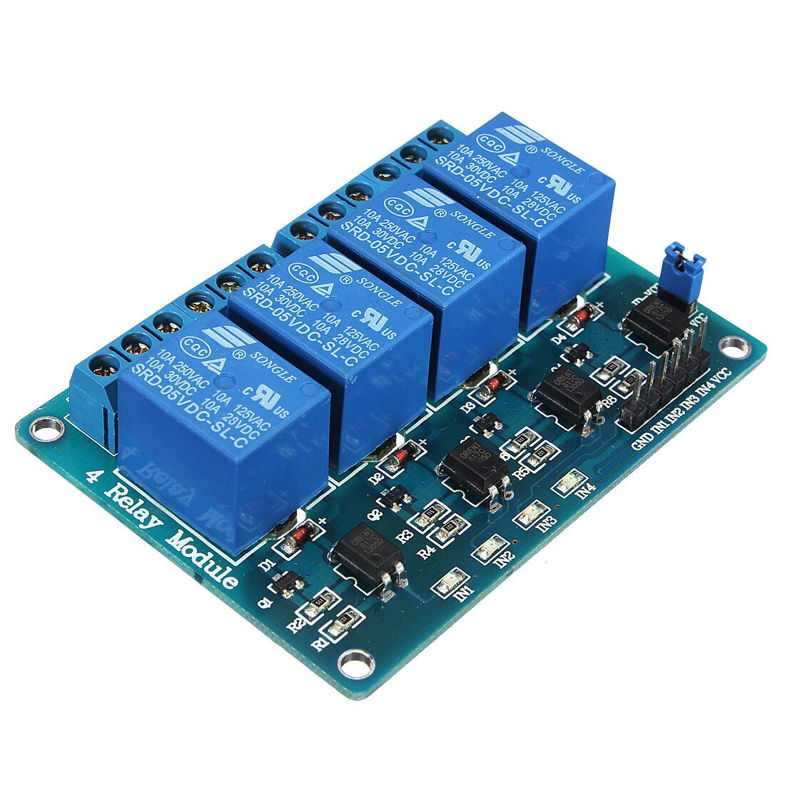
A 4-channel relay board using genuine Songle SRD-05VDC-SL-C mechanical relays — a very common, well-documented relay for hobby/Arduino projects. Each relay is a SPDT (single-pole double-throw) switch controlled by a 5V logic signal, letting a microcontroller switch mains-voltage or higher-current DC loads that its own GPIO pins could never handle directly.
Key specs
- Relay: Songle SRD-05VDC-SL-C, ×4
- Coil voltage: 5VDC
- Contact rating: 10A @ 250VAC / 125VAC, 10A @ 30VDC / 28VDC
- Configuration: SPDT per relay (NO/NC/COM screw terminals per channel)
- Channels: 4, independently controlled
- Logic input: 5V per channel (check board silkscreen/schematic for active-high vs. active-low triggering, and whether opto-isolation is present — not confirmed from the supplied photo)
Pinout
Per-channel screw terminal block (×4, one per relay):
| Terminal | Function |
|---|---|
| NO | Normally Open contact |
| COM | Common contact |
| NC | Normally Closed contact |
Control side: one GPIO-level input pin per channel, plus shared VCC/GND — exact header layout not fully legible from the supplied photo; check the board’s own silkscreen before wiring.
Wiring / typical usage
Use the screw terminals to switch an external load’s power path (COM to load, NO or NC depending on desired default state), and drive each channel’s control input from a GPIO. Never use this board to switch mains voltage (110V/220V AC) unless confident in the wiring, isolation, and enclosure safety — the relay itself is rated for it, but hobbyist mains wiring mistakes are a real fire/shock risk; low-voltage DC loads (motors, solenoids, lights) are the safer default use case for this library’s projects. Check whether the board is opto-isolated before assuming the logic side is safely separated from the switched side.
Code / libraries
N/A beyond simple digitalWrite() per channel — confirm active-high vs. active-low behavior on first test (most Songle relay boards of this style are active-LOW, but this isn’t confirmed for this specific board without checking the silkscreen or testing directly).
Source material
- Relay markings (Songle, SRD-05VDC-SL-C, contact ratings) read directly from the supplied photo — high confidence.
- Board brand/model (
inland,4Relaysilkscreen) read directly from the supplied photo. - Product photo:
/inventory/4ch-5v-relay-module-songle/product-photo.jpg— the actual owned unit, relay markings legible.
Verification
Relay part number and contact ratings read directly from the physical relay markings via photo — high confidence, this is a well-documented standard relay. Logic-side details (active-high/low, opto-isolation) are NOT confirmed — check the board's own silkscreen or test with a multimeter/logic probe before assuming polarity, since this varies across relay-board designs even when the relay itself is identical.
Notes / gotchas
- Confirm active-high vs. active-low triggering before wiring — driving the wrong polarity either does nothing or leaves the relay permanently energized.
- Mechanical relays are audibly and physically different from solid-state relays — expect an audible click and a finite mechanical switching lifetime (typically rated in the datasheet as switching cycles, not measured for this unit).
- If switching inductive loads (motors, solenoids), consider whether the board already has flyback protection or whether an external flyback diode is needed.